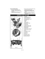


5. Thread the adjustment pivot pin along the
shift rod until it aligns with the mating hole
on the speed selector lever.
6. Support Sno-Thro frame and housing.
7. Remove top two cap screws and loosen
lower cap screws holding blower housing
to frame (one on each side).
6. Reinsert the pivot pin into the hole on the
speed selector lever.
8. Hold the brake away from the attachment
pulley and separate housing from unit.
Lower handlebar on floor.
7. Check forward and reverse speeds.
a. Start unit.
9. Remove attachment drive belt from lower
pulley (hold brake away from belt).
b. Shift speed selector into first forward
speed.
c. Engage traction clutch. Unit should
move forward.
2
1
d. Stop unit.
3
e. Shift speed selector into first reverse
speed.
f. Engage traction clutch. Unit should
move backward.
6
7
g. Shut off unit.
8. Adjust pivot pin as needed so unit travels
forward when speed selector lever is in
first forward position and backward when
speed selector lever is in first reverse
position.
9. Secure adjustment pivot pin to speed
selector lever with hairpin.
4
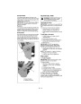
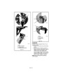
ATTACHMENT DRIVE BELT
REPLACEMENT
Remove Attachment Drive Belt
OS0802
5
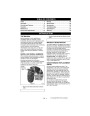
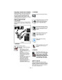
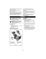
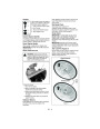
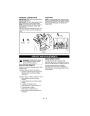
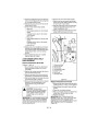
(Figures 17 and 18)
1. Pinion and Gear
2.
3. Chute Crank
4. Housing Bolt Holes
Spring Clip Pin
1. Shut off engine, remove key, disconnect
spark plug wire and allow unit to cool
completely.
5.
6.
7.
Bottom Cover
Belt Cover
Universal Joint
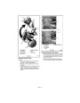
2. Remove two screws securing belt cover to
unit and remove belt cover.
3. Remove spring pin from chute crank rod
assembly at universal joint and separate.
4. Remove belt finger by removing cap screw
mounting belt finger to engine.
Figure 17
5. Remove attachment drive belt from engine
sheave (it may be necessary to turn
engine sheave using recoil starter
handle).
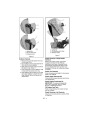
Replace Attachment Drive Belt
1. Place new belt onto lower pulley and while
holding brake out of way, tip unit together.
2. Secure blower housing to frame with cap
screws.
CAUTION: Always support
Sno-Thro frame and housing when
loosening the cap screws holding
them together. Never loosen cap
screws while unit is in service
position.
3. Place belt onto engine sheave.
4. Make sure engine sheave and attachment
pulley align, and belt rides on idler.
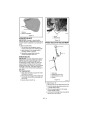
5. Replace belt finger.
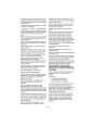
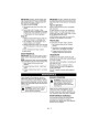
IMPORTANT: BELT FINGER MUST BE
between 1/16 to 1/8 in. (1.6–3 mm) from belt
with attachment clutch engaged or belt
grabbing may occur causing impeller to rotate
while attachment clutch is disengaged
(Figure 18).
IMPORTANT: To avoid bending bottom cover,
when tipping unit apart, support handlebars
firmly or tip unit up on housing and remove
bottom cover by removing four cap screws
before separating unit.
GB - 22
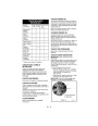
| Categories | Ariens Snow Blower Manuals, Snow Blower Manuals |
|---|---|
| Tags | Ariens 932105-8526, Ariens 932506-8526 |
| Download File |
|
| Document Type | Owner's Manual |
| Language | English |
| Product Brand | Ariens, Snow Blower |
| Document File Type | |
| Publisher | ariens.com |
| Wikipedia's Page | Ariens |
| Copyright | Attribution Non-commercial |
(0 votes, average: 0 out of 5)