
8.
9.
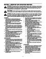
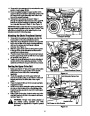
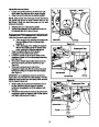
Reinsert the remaining hex screws removed in
Step 4 through the remaining aligning holes in both
the support carriage assembly and the tractor’s
frame rail (just behind the tractor’s front pivot
bracket). Securely fasten with the remaining lock
washers and hex nuts. See Figure 7.
Securely tighten all the other hardware used to
mount the support carriage assembly.
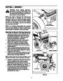
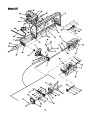
Mounting the Undercarriage Assembly
1.
Remove the carriage bolts, lock washers and hex
nuts from both sides of the front of the under-
carriage assembly.
Hex
Screw
2.
Carefully position the undercarriage assembly
right-side up beneath the tractor and stretch both
belts out toward the front of the tractor to keep them
from getting in the way of completing the following
steps.
Support Carriage Groove
Figure 7
NOTE: The zinc-plated double pulley is located in the
REAR of the undercarriage assembly.
3.
4.
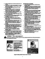
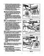
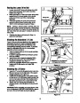
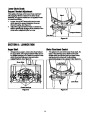
Position the slot found on both the left, rear and the
right, rear sides of the undercarriage onto the
tractor’s running board rod. See Figure 8.
Pivot the undercarriage upward allowing the
tractor’s front lift links to suspend between the
undercarriage’s left side plates and the tractor’s
frame rails. The tractor’s adjustable lift link (an ‘L’-
shaped rod found on the front, right) will suspend
through the opening in the right side of the
undercarriage.
NOTE: The rear lift links (See Figure 8) are unaffected
by this assembly and not used in any regard by the
snow thrower attachment. Both can be ignored.
Rear Lift Links
Running Board Rod
Front Lift Link NOTE: The tractor’s frame and running
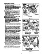
5.
With the undercarriage’s side plates positioned to
the inside of the support carriage mounted earlier,
reinsert the carriage bolts removed in step 1
through aligning holes in both the undercarriage
assembly and support carriage assembly. See
Figure 9.
board are ‘cut away’ for clarity in this figure.
Figure 8
6.
Secure the undercarriage to the support carriage
by refastening the lock washers and hex nuts
removed in Step 1 to the carriage bolts just
inserted.
NOTE: Disregard both the upper drive belt and the
lower drive belt at this point in the assembly of the snow
thrower. They will both be routed in later steps.
Attaching the Reflectors
Side Plate
1.
Peel off the backing from each of the reflectors to
expose the adhesive surface.
Carriage Bolts
2.
Adhere the reflectors to the rear of the tractor’s
fender (one on the left and one on the right) so that
the reflectors simulate taillights.
NOTE: The lock washer and hex nut are on
the INSIDE of the support carriage assembly.
Figure 9
7
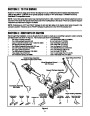
| Categories | MTD Snow Blower Manuals, Snow Blower Manuals |
|---|---|
| Tags | MTD 190-627, MTD Snow Blower Manual |
| Download File |
|
| Document Type | Owner's Manual |
| Language | English |
| Product Brand | MTD, Snow Blower |
| Document File Type | |
| Publisher | mtdproducts.com |
| Wikipedia's Page | MTD Products |
| Copyright | Attribution Non-commercial |
(0 votes, average: 0 out of 5)