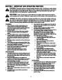
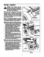
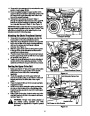
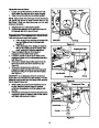

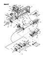
Attaching The Lift Handle
1.
Remove the hex screws and flange nuts from the
lower portion of the lift handle.
Vertical
Links
2.
Attach the lift handle to the lift bracket found on the
right side of the support carriage assembly with the
two hex screws and two flange lock nuts just
removed. See Figure 10.
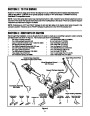
Mounting the Auger Housing Assembly
1.
Carefully remove the 2x4s placed under the
tractor’s front tires in Step 2 of Mounting the Support
Carriage Assembly.
2.
Position the auger housing assembly closely in
front of the tractor’s front-end.
Hex Screws
IMPORTANT: Having a second person assist you will
significantly ease the following steps.
Lift Handle
Figure 10
3.
Place the 2x4s removed in Step 1 beneath the
auger housing assembly’s lower lift links, just
behind the skid plate. This will cause the housing to
tilt slightly forward and ease in completing the
following steps.
4.
5.
Remove the clevis pin, flat washer and hairpin clip
from the lower portion of each vertical link on the
front of the support carriage assembly. See Figure
10.
Align the hole in the lower portion of each vertical
link with the hole found near the center of each of
the auger assembly’s lower lift links and reinsert
the clevis pins just removed through these aligned
holes.
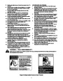
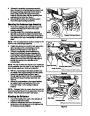
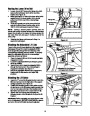
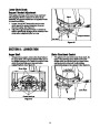
6.
Secure the vertical lift links to the lower lift links by
fastening with the flat washers and hairpin clips
also removed in Step 4. See Figure 11.
Vertical Link Secured
to Lower Lift Link
Auger Housing
Support Bar
7.
8.
Remove the hex screws, flat washers and crown
nuts from the rear portion of each lower lift link.
Grasp the auger housing support bar, refer to
Figure 11, on the left rear (have a second person
grasp the support bar on the right rear) portion of
the auger housing and lift upward until the holes
found on the rear of the lower lift links are aligned
with the holes found on both (left & right) sides of
the support carriage.
Figure 11
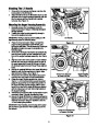
9.
Reinsert the hex screws (with one flat washer each)
removed in Step 7 through the aligning holes.
Secure the lower lift links to the support carriage by
fastening with the crown nuts and remaining two flat
washers removed in Step 8 in addition to the two
1¼-inch cotter pins provided.
10.
IMPORTANT: After inserting, bend the tips of the cotter
pins outward to prevent them from backing out of the
hex screws.
Lower Lift Link Secured
to Support Carriage
Figure 12
8
| Categories | MTD Snow Blower Manuals, Snow Blower Manuals |
|---|---|
| Tags | MTD 190-627, MTD Snow Blower Manual |
| Download File |
|
| Document Type | Owner's Manual |
| Language | English |
| Product Brand | MTD, Snow Blower |
| Document File Type | |
| Publisher | mtdproducts.com |
| Wikipedia's Page | MTD Products |
| Copyright | Attribution Non-commercial |
(0 votes, average: 0 out of 5)