
11.
12.
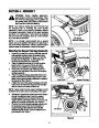
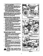
Remove the hex screws and hex nuts from the rear
portion of each upper lift link.
Have an assistant grasp the upper portion of the
auger housing and pivot the assembly upward until
the holes of the upper links align with holes in the
front of the support carriage.
13.
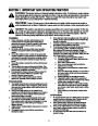
Reinsert the hex screws removed in Step 11
through the aligning holes and secure the upper lift
links to the support carriage by fastening with the
hex nuts also removed in Step 12. See Figure 13.
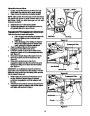
IMPORTANT: Make certain that the hex nut securing the
left upper lift link is positioned to the INSIDE of link. This
will avoid any interference when attaching the chute
directional control in following steps.
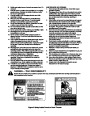
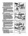
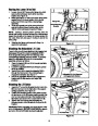
Attaching the Chute Directional Control
Upper Lift Link Secured
to Support Carriage
1.
Remove the hex screws and flange nuts from the
lower portion of the chute directional control.
Attach the chute directional control to the upper lift
link on the left side of the auger housing assembly
with two hex screws and two flange nuts just
removed. See Figure 14.
Figure 13
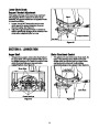
2.
Upper
Rod
3.
4.
5.
Slide the upper chute crank rod through the eyelet
in the top of the chute directional control and the
eyebolt found midway down.
Pivot the lower chute crank rod upward and secure
it to the upper chute crank rod with the ¾-inch cotter
pin provided. See Figure 14.
Fasten the chute tilt cables to the chute directional
control with the three cable ties provided. Pull the
cable ties until they’re snug and trim off any excess.
Lower
Rod
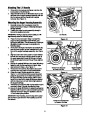
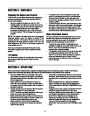
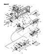
Routing the Upper Drive Belt
Hex Screws
1.
Make sure that the “V” side of the upper drive belt is
seated firmly in the upper portion of the double
pulley found in the rear of the undercarriage
assembly.
Chute Directional Control
Figure 14
2.
Route the opposite end of the upper drive belt
around the engine pulley, to the INSIDE of the belt
keeper pins found on either side of the engine
pulley.
Hook Extension Spring Here
3.
4.
Place the tractor’s lift lever in the lowest reachable
engagement notch.
Hook one end of the extension spring provided into
the hole on the left side of the undercarriage idler
bracket’s surface, just to the rear of the belt keeper.
See Figure 15
5.
Using a pair of vise grips, hook the other end of the
extension spring to a hole in the tractor’s left frame
rail. See Figure 15.
WARNING: Always wear safety glasses or
eye shields during operation and while
performing an adjustment or repair to protect
your eyes.
Double Pulley
Belt Keeper on Idler Bracket
Figure 15
9
| Categories | MTD Snow Blower Manuals, Snow Blower Manuals |
|---|---|
| Tags | MTD 190-627, MTD Snow Blower Manual |
| Download File |
|
| Document Type | Owner's Manual |
| Language | English |
| Product Brand | MTD, Snow Blower |
| Document File Type | |
| Publisher | mtdproducts.com |
| Wikipedia's Page | MTD Products |
| Copyright | Attribution Non-commercial |
(0 votes, average: 0 out of 5)