


•
•
•
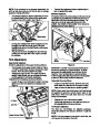
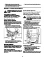
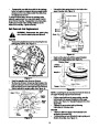
Back out the stop bolt until the support bracket
rests on the auger pulley. See Figure 20.
Slip belt between friction wheel and friction wheel
disc. See Figure 20. Remove and replace belt.
Reassemble following the instructions in reverse
order.
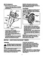
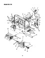
Screws
Friction Wheel Rubber
Hub
Screws
NOTE: The support bracket must rest on the stop bolt
after the new belt has been assembled. See Figure 20.
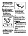
Servicing Friction Wheel Rubber
The rubber on the friction wheel is subject to wear and
should be checked after 25 hours of operation, and
periodically thereafter. Replace the friction wheel
rubber if any signs of wear or cracking are found.
Friction Wheel Plates
Figure 22
•
•
Reassemble new friction wheel rubber to the
friction wheel plates and hub, tightening the six
screws in rotation and with equal force.
Position the friction wheel assembly up onto the pin
of the shift rod assembly, and slide the shaft
through the assembly. Reassemble in reverse
order.
•
•
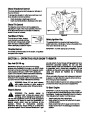
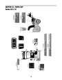
Drain the gasoline from the snow thrower.
Tip the snow thrower up and forward, so that it rests
on the housing.
•
•
•
Remove six self-tapping screws from the frame
cover underneath the snow thrower.
Remove the click pins which secure the wheels,
and remove the wheels from the axle.
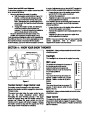
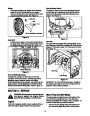
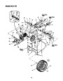
Using a 7/8" wrench to hold the shaft, loosen, but
do not completely remove, the hex nut and bell
washer on the left end of gear shaft. See Figure 21.
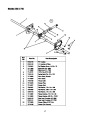
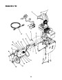
Augers
The augers are secured to the spiral shaft with two
shear bolts and hex lock nuts. Refer to Figure 14. If you
hit a foreign object or ice jam, the snow thrower is
designed so that the bolts mayshear. If the augers will
not turn, check to see if the bolts have sheared.
Hex Nut /
Bell Washer
IMPORTANT: NEVER replace the auger shear bolts with
standard hex bolts. Any damage to the auger gearbox
or other components as a result of doing so will NOT be
coved by your snow throwers warranty.
Off-season Storage
WARNING: Never store engine with fuel in
tank indoors or in poorly ventilated areas,
where fuel fumes may reach an open
flame, spark or pilot light as on a furnace,
water heater, clothes dryer or other gas
appliance.
•
If unit is to be stored over 30 days, prepare engine
for storage as instructed in the separate engine
manual packed with your unit.
NOTE: Snow thrower shown resting on its
auger housing. Wheels not shown for clarity.
•
•
•
Remove all debris from the exterior of the engine
and equipment.
Follow the lubrication recommendations found in
Section 7 of this manual.
Figure 21
•
Lightly tap the hex nut to dislodge the ball bearing
from the right side of frame before removing the hex
nut and bell washer from left end of shaft.
Move the gear shaft to the right and slide the friction
wheel assembly from the shaft.
Remove the six screws from the friction wheel
assembly (three from each side). Remove the
friction wheel rubber from between the friction
wheel plates. See Figure 22.
Always store the snow thrower in a clean, dry area.
•
•
NOTE: When storing any type of power equipment in
an unventilated or metal storage shed, care should be
taken to rust proof the equipment. Using a light oil or
silicone, coat the equipment, especially any chains,
springs, bearings and cables.
14
| Categories | MTD Snow Blower Manuals, Snow Blower Manuals, White Outdoor Snow Blower Manuals |
|---|---|
| Tags | MTD 550, MTD H623D, MTD H633E, MTD Snow Blower Manual, MTD Snow Boss 750, White Outdoor H623D, White Outdoor H633E, White Outdoor Snow Boss 550, White Outdoor Snow Boss 750 |
| Download File |
|
| Document Type | Owner's Manual |
| Language | English |
| Product Brand | MTD, Snow Blower |
| Document File Type | |
| Publisher | mtdproducts.com |
| Wikipedia's Page | MTD Products |
| Copyright | Attribution Non-commercial |
(0 votes, average: 0 out of 5)