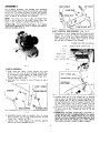


For
shipping
purposes,
the
handles
and
operating
controls
of your snow thrower have not been assembled
to the unit. The carton of parts, in which this owner's
was found, all components and hard-
to complete the assembly.
manual
contains
ware
necessary
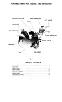
NOTE:
(R.H).
stand
The
refer
in the operator's
terms
Left
left
Hand
and
position
(L.H.)
right
behind the unit.
and
hands when you
Right
Hand
to
your
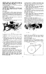
ATTENTION:
THROWER
FOR EASIER SNOW
FORWARD SO THAT IT RESTS ON SAFETY
ASSEMBLY,
TILT
BAR AS SHOWN (FIG. 2).
FIG. 4
SHIFT
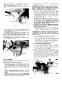
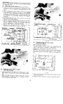
CONTROL ROD ASSEMBLY (Fig. 5 to 8)
3fs -16 flange (A) to end of shift
1.
Assemble
one
nut
control
Flange
rod
having
must
the
face
longest
toward
threaded portion.
threaded end of
of
nut
shift
control
rod as shown (Fig. 5 and 6). Thread
the nut the full
length of the threads.
TRANSMISSION
CONTROL
BRACKET
(C)
'Z'
SLOT
PLATE
PIN
HANDLE
LOCATING
SHIFT
CONTROL
ROD
HANDLE
ASSEMBLY
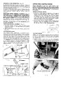
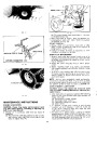
1.
Slide
screws
lower
on R.H. side of snow thrower
two
holes
of
R.H.
handle
over
chassis
weld
weld
(Fig.
screw,
3).
Assemble
formed
handle
tight
washer
with
only.
to upper
two
SHIFT
CONTROL
ROD________
A
and
Tighten
secure
finger
3fs -16 flange nuts.
TRANSMISSION
CONTROL
BKT.
~.....
/
2.
Assemble
manner.
L.H.
handle
to
snow
thrower
in
same
CHASSIS
r'0
FORMED
WASHER
TRANSMISSION
SHIFT~~.
~~
~
RIGHT
HANDLE
~.:y
/
~I
/
~~~\
\ \ .~
!
FIG. 6
~~~~f*
c'
rn~
2.
Position
other
end of shift
control
rod up through
slot
in top of handle plate, so that
locating
pin on
\
"'"· -J
rod engages
the
"Z"
slot
control
end
in handle
bracket
plate
upwards
(Fig. 5).
(Fig.
Swing
transmission
6),
and
insert
lower
of shift
control
rod
into
hole in transmission (Fig. 5 and 6).
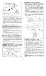
3fs -16 flange nut (B), with
end of shift rod (Fig. 6). Do not
control
bracket
\
WELD
SCREWS
@
FLANGE
NUTS
3.
4.
Assemble
one
flange
up,
to
lower
control
tighten
nut.
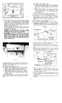
IMPORTANT:
Position
transmission
shift
lever
in
neutral
of slot in rear cover. Rotate wheels of unit;
should turn freely if neutral has been obtained.
position (Fig. 7), approximately in the centre
wheels
Shift
may have to be moved up or down slightly
of slot in order to obtain neutral.
3.
4.
Assemble
four
handle
plate
to
carriage
securely.
handles
(Fig.
4), using
5/16-18
5/16-18 x 1 ¥.i
bolts
and four
flange
nuts. Tighten
lever
from
Tighten
lower end of both handles (Fig. 3).
four
3fs -16
flange
nuts
securely
against
centre
| Categories | Craftsman Snow Blower Manuals, Snow Blower Manuals |
|---|---|
| Tags | Craftsman C944.526460 |
| Model Number | C944.526460 |
| Download File |
|
| Document Type | Operator's Manual |
| Language | English |
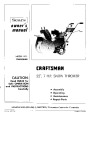
| Product Name | Craftsman 22-Inch Snow Thrower |
| Product Brand | Craftsman. Customer Service Representatives are available by phone: Canada 1-888-225-4886 USA 1-888-384-9939, Snow Blower |
| Product Type | Snowthrower |
| Swath | 22 inch |
| Engine Manufacturer | Craftsman |
| Engine Oil Type | SAE 5W30 |
| Engine Motor Model # | 143.666302 |
| Tire Pressure | Correct tire pressure is 20 to 25 P.S.1. Keeping tires at correct pressure will assure good traction. |
| Document File Type | |
| Publisher | craftsman.com |
| Wikipedia's Page | Craftsman (tools) |
| Copyright | Attribution Non-commercial |
(0 votes, average: 0 out of 5)