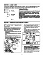
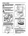


Drive Belt
Screws
•
•
•
•
•
Follow the first four steps of the instructions for
servicing the auger belts.
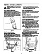
Pull idler pulley up, and lift belt off engine pulley and
friction wheel disc. See Figure 17.
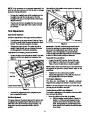
Back out the stop bolt until the support bracket
rests on the auger pulley. See Figure 19.
Slip belt between friction wheel and friction wheel
disc. See Figure 19. Remove and replace belt.
Reassemble following the instructions in reverse
order.
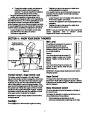
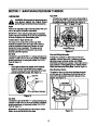
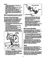
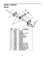
Friction Wheel Rubber
Hub
Screws
Friction Wheel Plates
NOTE: The support bracket must rest on the stop bolt
after the new belt has been assembled. See Figure 19.
Figure 21
•
Remove the six screws from the friction wheel
assembly (three from each side). Remove the
friction wheel rubber from between the friction
wheel plates. See Figure 21.
Servicing Friction Wheel Rubber
The rubber on the friction wheel is subject to wear and
should be checked after 25 hours of operation, and
periodically thereafter. Replace the friction wheel
rubber if any signs of wear or cracking are found.
•
•
Reassemble new friction wheel rubber to the
friction wheel plates and hub, tightening the six
screws in rotation and with equal force.
•
•
Drain the gasoline from the snow thrower.
Tip the snow thrower up and forward, so that it rests
on the housing.
Position the friction wheel assembly up onto the pin
of the shift rod assembly, and slide the shaft
through the assembly. Reassemble in reverse
order.
•
•
•
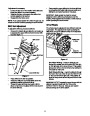
Remove six self-tapping screws from the frame
cover underneath the snow thrower.
Remove the click pins which secure the wheels,
and remove the wheels from the axle.
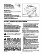
Using a 7/8" wrench to hold the shaft, loosen, but
do not completely remove, the hex nut and bell
washer on the left end of gear shaft. See Figure 20.
Shave Plate and Skid Shoes
The shave plate and skid shoes on the bottom of the
snow thrower are subject to wear. They should be
checked periodically and replaced when necessary. To
remove the skid shoes, proceed as follows:
Hex Nut /
Bell Washer
•
Remove the four carriage bolts, bell washers and
hex nuts which attach them to the snow thrower.
•
Reassemble new skid shoes with the four carriage
bolts, bell washers (cupped side goes against skid
shoes) and hex nuts. Make certain the skid shoes
are adjusted to be level.
To remove shave plate, remove the carriage bolts,
belleville washers and hex nuts which attach it to the
snow thrower housing. Reassemble new shave plate,
making sure heads of the carriage bolts are to the
inside of the housing. Tighten securely.
Augers
The augers are secured to the spiral shaft with two
shear bolts and hex lock nuts. Refer to Figure 14. If you
hit a foreign object or ice jam, the snow thrower is
designed so that the bolts may shear. If the augers will
not turn, check to see if the bolts have sheared.
NOTE: Snow thrower shown resting on its
auger housing. Wheels not shown for clarity.
Figure 20
•
•
Lightly tap the hex nut to dislodge the ball bearing
from the right side of frame before removing the hex
nut and bell washer from left end of shaft.
Move the gear shaft to the right and slide the friction
wheel assembly from the shaft.
IMPORTANT: NEVER replace the auger shear bolts with
standard hex bolts. Any damage to the auger gearbox
or other components as a result of doing so will NOT be
covered by your snow throwers warranty.
14
| Categories | MTD Snow Blower Manuals, Snow Blower Manuals |
|---|---|
| Tags | MTD E663G, MTD Snow Blower Manual |
| Download File |
|
| Document Type | Owner's Manual |
| Language | English |
| Product Brand | MTD, Snow Blower |
| Document File Type | |
| Publisher | mtdproducts.com |
| Wikipedia's Page | MTD Products |
| Copyright | Attribution Non-commercial |
(0 votes, average: 0 out of 5)