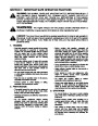
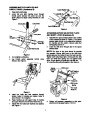
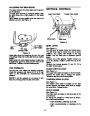


ATTACHING THE CLUTCH CABLES
(Hardware D)
Note: Lock nuts cannot be threaded onto a bolt by
hand. Tighten with 2 7/16” wrenches. This type of
nut is used where vibration occurs.
1.
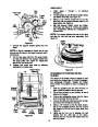
Thread hex nuts (J) onto the “Z” fittings (R) (see
inset,). Insert “Z” fitting into hole in clutch grips.
See Figure 6.
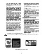
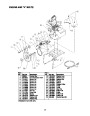
Chute
Assembly
Hex Bolt
“Z” Fitting
(R)
Hex Lock Nut
Hex
Nut
(J)
Chute Flange
Keeper
Figure 7
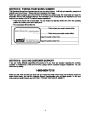
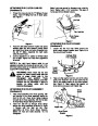
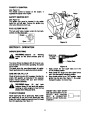
ATTACHING THE CHUTE CRANK
(Hardware F)
Figure 6
2.
3.
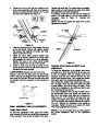
Route the left cable between engine and speed
selector plate and then between handle panel
and clutch lever pivot rod before threading onto
the left “Z” fitting. Assemble the right cable
using the same route.
1. Loosen the two hex nuts which secure the
chute crank support bracket (see Figure 8) to
the snow thrower housing.
Carriage Bolts
Hex Lock Nuts
Correct adjustment on cables is minimal slack
but not tight. Tighten hex nuts when adjustment
is correct.
NOTE: If the right hand lockout cable is not
adjusted correctly, the wheels will tend to turn. If the
left hand lockout cable is not adjusted correctly, the
augers will not stop rotating.
Lower
Chute
Crank
Bracket
WARNING: There must not be any
tension on either clutch cable with the
Figure 8
drive
or auger clutch grip in the
disengaged
clutches are a safety feature, and their
function can be overridden if there is
(up)
position.
These
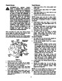
2. Place one flat washer over the end of the chute
crank, then insert the end of the crank into the
hole in the plastic bushing in the chute bracket.
See Figure 9. Place second flat washer on
chute crank, and secure with hairpin clip.
tension
on
either
cable
with
the
clutches disengaged.
Flat
Washer
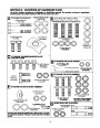
ATTACHING THE CHUTE ASSEMBLY
(Hardware E)
Chute
Crank
1.
Place chute assembly over chute opening, with
the opening in the chute assembly facing the
front of the unit. Place chute flange keepers
beneath lip of chute assembly, with the flat side
of chute flange keeper facing downward.
2.
Insert hex bolt (K) up through chute flange
keeper and chute assembly as shown in Figure
Hairpin Clip
7.
Secure
with
hex
lock
nut
(M).
After
assembling all three chute flange keepers,
tighten all nuts and bolts securely. Do not
overtighten.
Chute Crank
Bracket
Figure 9
8
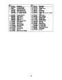
| Categories | MTD Snow Blower Manuals, Snow Blower Manuals, Yard Machines Snow Blower Manuals |
|---|---|
| Tags | MTD 615, MTD E645E, MTD E665E, MTD Snow Blower Manual, Yard Machines 615, Yard Machines E645E, Yard Machines E665E |
| Download File |
|
| Document Type | Owner's Manual |
| Language | English |
| Product Brand | MTD, Snow Blower, Yard Machines, 615, E645E, E665E, Snow Blower |
| Document File Type | |
| Publisher | mtdproducts.com |
| Wikipedia's Page | MTD Products |
| Copyright | Attribution Non-commercial |
(0 votes, average: 0 out of 5)