


•
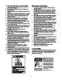
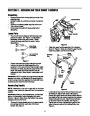
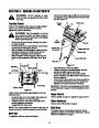
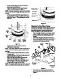
Slide the shift rod connector down over the end of
the lower shift rod. See Figure 4. Tap the connector
until it locks on the lower shift rod.
Lower Handle
Conduit
NOTE: If the connector is not properly assembled, the
shift rod will pivot and you will not be able to change
direction or speed of the snow thrower.
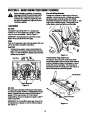
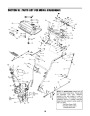
Power Lead
Wiring
Harness
Connector
Figure 6
Lower
Shift Rod
Final Adjustments
Upper Shift
Rod
Traction Control and Shift Lever
To check the adjustment of the traction control and shift
lever, proceed as follows:
•
•
Move the shift lever into sixth (6) position.
With traction control released, gently push the
snow thrower forward, then pull it back. The
machine should move freely.
•
•
Engage traction control, and try to move the
machine both forward and back. You should
experience resistance.
Move the shift lever into the fast reverse (R2)
position and repeat the previous two steps.
Note: Cut-out view of lower handle shown for clarity.
Figure 4
•
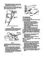
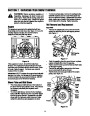
If not already attached, slip the cables that run from
the handle panel to the chute into the cable guide
located on top of the engine. See Figure 5.
If you experienced resistance either when repositioning
the shift lever from 6 to R2 or when attempting to move
the machine with the traction control released, adjust
the traction control immediately. To adjust, proceed as
follows:
Cable Guide
•
Loosen the jam nut on the traction control cable
and UNTHREAD the cable one full turn.
Recheck adjustment.
Retighten the jam nut to secure the cable when
correct adjustment is reached.
•
•
NOTE: For more details, refer to Traction Control
Adjustment on page 12.
Auger Control
Check the adjustment of the auger control as follows:
•
Push down on the auger control until the small
rubber bumper contacts the upper handle. There
should be slack in the auger control cable.
Release the auger control. The cable should be
straight. Make certain you can depress the auger
control against the left handle completely.
Figure 5
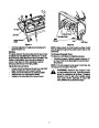
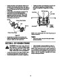
If for shipping purposes the wiring harness was left
unattached to the power lead, follow the steps below to
attach it now:
•
•
Follow the conduit that holds the wiring harness
from under the right side of the handle panel to
where the connectors are located at the bottom of
the right hand lower handle. See Figure 6.
Plug the wiring harness into the power lead located
on the right side of the engine, underneath the fuel
tank. See Figure 6 inset.
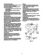
If adjustment is necessary, proceed as follows:
•
Loosen the jam nut and thread the cable in (for less
slack) or out (for more slack) as necessary. See
Figure 7.
•
6
| Categories | MTD Snow Blower Manuals, Snow Blower Manuals, Yard Man Snow Blower Manuals |
|---|---|
| Tags | MTD 31AH553G401, MTD Snow Blower Manual, Yard Man 31AH553G401 |
| Download File |
|
| Document Type | Owner's Manual |
| Language | English |
| Product Brand | Yard-Man, 31AH553G401, Snow Blower |
| Document File Type | |
| Publisher | mtdproducts.com |
| Wikipedia's Page | MTD Products |
| Copyright | Attribution Non-commercial |
(1 votes, average: 3 out of 3)
Lawn and Garden readers have rated Yard-Man 31AH553G401 Snow Blower Owners Manual by MTD 3.0 out of 3.0 based on 1 product reviews. Had a time getting into sight review awful