damage
in
otherwise
healthy
people.
If
responsible for maintaining the operating
condition of these parts. Failure to do so is
a violation of the law. Refer to the SERVICE
symptoms occur such as numbness, pain,
loss ofstrength,changeinskincolor ortexture,
or loss offeeling inthe fingers,hands, or joints,
discontinue the use of this tool and seek
medical attention. An anti-vibration system
does not guarantee the avoidance of these
problems. Users who operate power tools on
a continual and regular basis must monitor
section
for maintenance of the spark
arresting screen.
FailuretofollowallSafetyRules andPrecau-
tions canresult inserious injury. Ifsituations
occur which are not covered in this manual,
use care and good judgement. If you need
assistance, contact your authorized service
dealer or call 1-800--554--6723.
closely
their physical condition and the
condition of this tool.
SPECIALNOTICE:Yoursaw isequipped
STANDARDS: This saw is listed by Under-
with a temperature limiting muffler andspark
the
writer’s Laboratories, Inc., in accordance with:
B175.1--2000 American National
for Gasoline--Powered Chain
arresting
screen
which
meets
ANSI
requirements of California Codes 4442 and
Standards
4443.
All U.S. forest land and the states of
Saws -- Safety Requirements
CSA Z62.1--03 Chain Saws -- Occupational
Health and Safety
California, Idaho, Maine, Minnesota, New
Jersey, Oregon, and Washington require by
law that many internal combustion engines
tobeequippedwithaspark arrestingscreen.
Ifyouoperateachainsaw inastate or locale
wheresuchregulations exist,you arelegally
CSA Z62.3--96 Chain Saw Kickback Occu-
pational Health and Safety
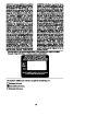
ASSEMBLY
Protective gloves (not provided) should be
worn during assembly.
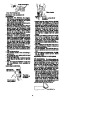
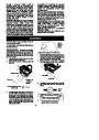
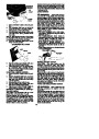
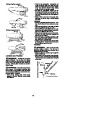
ATTACHINGTHEBAR&CHAIN (Ifnot
already attached)
Inside
view of
clutch
cover
WARNING:
If received assembled,
repeat all steps to ensure your saw is properly
assembled and all fasteners are secure. Al-
ways wear gloves when handling the chain.
Thechainis sharp andcan cutyou evenwhen
it is not moving!
Adjustment located on clutch cover
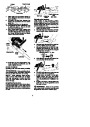
4.
Turn the adjusting screw by hand coun-
terclockwise until the adjusting pin just
touches the stop. This should allow the
pin to be near the correct position.
1.
Loosenandremovethebar nuts andthe
clutch cover from the saw.
Remove the plastic shipping spacer (if
present).
5.
Slide guide bar on bar bolts until guide
bar stops against clutch drum sprocket.
2.
Clutch cover
Bar bolts
Guide bar
Bar nuts
Location of
shipping
spacer
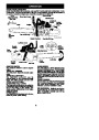
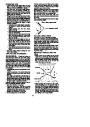
6.
Carefully remove the chainfrom thepack-
age. Hold chain with the drive links as
shown.
Chain adjustment tool
(Bar Tool)
Tip of
Bar
3.
An adjusting pin and screw is used to ad-
just the tension of the chain. It is very im-
portant when assembling the bar, that the
pin located on the adjusting screw aligns
intoaholeinthebar.Turningthescrewwill
move the adjustment pin up and down the
screw. Locate this adjustment before you
begin mounting the bar onto the saw. See
following illustration.
CUTTERS MUST FACE IN
DIIRECTION OF ROTATION
6
| Categories | Chainsaw Manuals, Poulan Chainsaw Manuals |
|---|---|
| Tags | Poulan S1970 |
| Model Year | 2003 |
| Download File |
|
| Document Type | Owner's Manual |
| Language | English |
| Product Brand | Poulan. Poulan US phone support. Wheeled (Mowers, Tractors, Tillers): 1-800-849-1297 Handheld (Chainsaws, Trimmers): 1-800-554-6723 , Chainsaw |
| Document File Type | |
| Publisher | poulan.com |
| Wikipedia's Page | Poulan |
| Copyright | Attribution Non-commercial |
(0 votes, average: 0 out of 5)