
SERVICE AND ADJUSTMENTS
1.
2.
3.
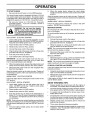
Disengage all controls and move throttle control to
STOP position. Wait for all moving parts to stop.
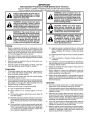
WARNING: To avoid serious injury,
before performing any service or ad-
justments:
Disconnect spark plug wire from spark plug and place
wire where it cannot come in contact with plug.
1.
2.
3.
Be sure throttle is in STOP position.
Remove safety ignition key.
Align holes in impeller hub with holes in impeller shaft
and install two (2) new 1/4-20 x 1-5/8" capscrew/shear
bolts. Install 1/4-20 locknuts and tighten securely.
Make sure the augers and all moving
parts have completely stopped.
CAUTION: Do not substitute. Use only original
equipment capscrew/shear bolts as supplied
with your snow thrower.
4.
Disconnect spark plug wire from
spark plug and place wire where it
cannot come in contact with plug.
4.
Connect spark plug wire to spark plug.
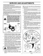
SNOW THROWER
TO ADJUST SNOW THROWER HEIGHT
1/4-20
LOCKNUT
1/4-20 x 1-5/8
CAPSCREW /
SHEAR BOLT
1/4-20 x 2
SHOULDER /
SHEAR BOLT
See “TO ADJUST SKID PLATES” and “SCRAPER BAR”
in the Operation section of this manual.
SPACER
IMPELLER HUB
IMPELLER
SHAFT
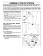
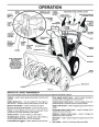
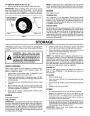
CHUTE DEFLECTOR
The chute deflector, attached to the top of the discharge
chute, is provided to direct discharging snow away from
the operator. If the deflector becomes damaged, it should
be replaced.
WARNING: To avoid serious injury,
never operate your snow thrower with
the deflector removed or damaged.
•
Tochangedirectionand/ordistancesnowisdischarged,
see “TO CONTROL SNOW DISCHARGE” in the Op-
eration section of this manual.
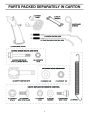
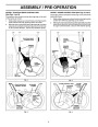
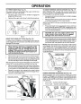
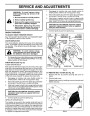
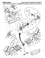
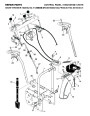
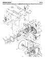
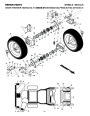
AUGER
HUB
SHEAR BOLTS (See Fig. 22)
AUGER SHEAR BOLTS
1/4-20
LOCKNUT
AUGER HUB
AUGER SHAFT
Both right and left-hand augers are secured to the auger
shaft with a shoulder/shear bolt and hex nut. Should a for-
eign object or ice become lodged in the augers, the shear
bolts are designed to break, preventing damage to any
other components. If one or both augers do not turn when
auger control lever is engaged, check to see if one or both
of the bolts have sheared. To replace the shear bolts:
FIG. 22
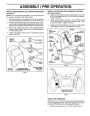
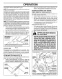
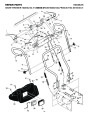
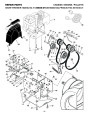
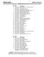
TO REMOVE BELT COVER (See Fig. 23)
1. Remove the two (2) screws securing belt cover to
frame.
1.
2.
3.
Disengage all controls and move throttle control to
STOP position. Wait for all moving parts to stop.
2. Remove belt cover.
•
Replace belt cover by installing cover and screws and
tighten securely.
Disconnect spark plug wire from spark plug and place
wire where it cannot come in contact with plug.
Alignholeinaugerhubwithholeinaugershaftandinstall
anew1/4-20x2"shoulder/shearboltwithspacer.Install
BELT
COVER
1/4-20
lock nut and tighten securely.
CAUTION: Do not substitute. Use only original
equipment shear bolts as supplied with your
snow thrower.
4.
Connect spark plug wire to spark plug.
IMPELLER SHEAR BOLTS
The impeller is secured to the impeller shaft with two (2)
capscrew/shearboltsandhexnuts.Shouldaforeignobject
or ice become lodged in the impeller, the capscrews are
designed to break, preventing damage to any other com-
ponents. If impeller does not turn when auger control lever
is engaged, check to see if the capscrews have sheared.
To replace the capscrew/shear bolts:
FRAME
SCREWS
16
FIG. 23
| Categories | Husqvarna Snow Blower Manuals, Snow Blower Manuals |
|---|---|
| Tags | Husqvarna 1130SBE-OV |
| Model Year | 2006, 2007, 2008, 2009 |
| Download File |
|
| Document Type | Owner's Manual |
| Language | English |
| Product Brand | Husqvarna, Snow Blower |
| Document File Type | |
| Publisher | husqvarna.com |
| Wikipedia's Page | Husqvarna |
| Copyright | Attribution Non-commercial |
(0 votes, average: 0 out of 5)