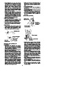
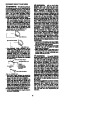
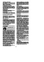
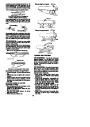
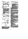
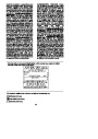
move the adjustment pin up and down the
screw. Locate this adjustment before you
begin mounting the bar onto the saw. See
following illustration.
Clutch
Cover
Inside
view of
clutch
cover
Adjusting Pin
Adjustment located on clutch cover
Lower
Hole
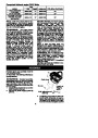
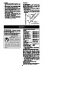
4.
Turn the adjusting screw by hand coun-
terclockwise until the adjusting pin just
touches the stop. This should allow the
pin to be near the correct position.
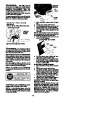
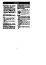
Guide Bar
5.
Slide guide bar on bar bolts until guide
bar stops against clutch drum sprocket.
12.
Install bar nuts and finger tighten only.
Once the chain is tensioned, you will
need to tighten bar nuts.
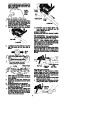
CHAIN TENSION
(Including units with chain already installed)
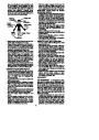
WARNING: Wear protectivegloves
whenhandlingchain. Thechainis sharpand
can cut you even when it is not moving.
Bar bolts
NOTE:
When adjusting chain tension,
make sure the bar nuts are finger tight only.
Attemptingto tensionthe chainwhen thebar
nuts are tight can cause damage.
Guide bar
6.
Carefully remove the chainfrom thepack-
age. Hold chain with the drive links as
shown.
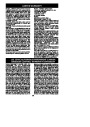
Checking the tension:
Use the screwdriver end of the chain adjust-
ment tool (bar tool) to move chain around
guidebar.Ifthechaindoes notrotate,itistoo
tight. Ifthechainis tooloose,itwillsagbelow
the bar.
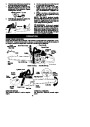
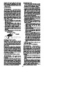
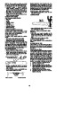
Tip of
Bar
Guide
Bar
CUTTERS MUST FACE IN
DIIRECTION OF ROTATION
Chain Adjustment
Tool
(Bar Tool)
Depth Gauge
Cutters
Bar Nuts
Adjusting
Screw
Adjusting the tension:
Chain tension is very important. Chains
stretch during use. This is especially true
during the first few times you use your saw.
Always check chain tension each time be-
fore you start the chain saw.
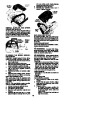
Drive Links
7.
8.
Place chain over and behind clutch re-
tainer, fitting the drive links in the clutch
drum sprocket.
1.
Loosenbar nutsuntiltheyarefingertight
against the clutch cover.
Turn adjusting screw clockwise untilchain
solidly contacts bottom of guide bar rail.
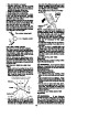
Fit bottom of drive links between the
teeth in the sprocket in the nose of the
guide bar.
2.
9.
10.
Fit chain drive links into bar groove.
Pullguidebar forward untilchain is snug
in guide bar groove. Ensure all drive
links are in the bar groove.
Adjusting
Screw
11.
Now, install clutch cover making sure
theadjusting pinis positionedin thelow-
er hole in the guide bar. Remember this
pin moves the bar forward and back-
ward as the screw is turned.
7
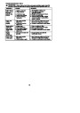
| Categories | Chainsaw Manuals, Poulan Chainsaw Manuals |
|---|---|
| Tags | Poulan BH, Poulan P3314, Poulan P3314WS, Poulan P3314WSA, Poulan P3416, Poulan P3516PR, Poulan P3818AV, Poulan P4018AV, Poulan P4018WM, Poulan P4018WT |
| Model Year | 2010 |
| Download File |
|
| Document Type | Owner's Manual |
| Language | English |
| Product Brand | Poulan. Poulan US phone support. Wheeled (Mowers, Tractors, Tillers): 1-800-849-1297 Handheld (Chainsaws, Trimmers): 1-800-554-6723 , Chainsaw |
| Document File Type | |
| Publisher | poulan.com |
| Wikipedia's Page | Poulan |
| Copyright | Attribution Non-commercial |
(0 votes, average: 0 out of 5)