


3
Assembling
Your Tiller
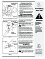
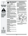
Attaching Control Rod
Slot Head Screw, Nut,
Flat Washers
&
•
•
•
Make sure the handle assembly is in the highest
position. Refer to Know Your Tiller section.
TInternallyhreaded Tube
Remove hairpin clips from control rod, (rubber
washers to remain on control rod).
Insert the shorter, (angled), end of the control rod
through the indicator bracket on the shift cover and
secure with hairpin clip that was previously removed.
See Figure 3-5.
•
Insert the longer end of the control rod through the
hole in the gear selector handle and secure with
hairpin clip.
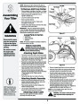
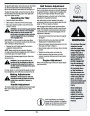
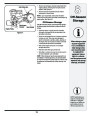
Final Clutch Adjustment
IMPORTANT: Service the engine with oil and gasoline
before checking this adjustment. Refer to the separate
engine manual packed with your tiller for proper fuel and
engine oil recommendations.
Plastic Fitting
Figure 3-3
Position the tiller so the front counterweight is against
a solid object, such as a wall. With the gear selection
lever in NEUTRAL, start the engine. Refer to the
separate engine manual.
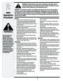
WARNING
Slot Head Screw
Flat Washers
Nut
Clutch Control
Do not put your
fingers under the
belt cover.
Standing on the right side of the tiller, examine the belt
(inside the belt cover). It should not be turning.
Threaded
Eyebolt
WARNING:the belt covDoer. not put your fingers under
Maximum tire
pressure under any
circumstances is
Nut
If the belt turns without bail engaged, adjust by
unthreading the internally threaded tube at the end
of the cable a few turns clockwise (when standing in
operator’s position) and then retighten the nut against
the tube.
Now move the shift lever to FORWARD position.
Carefully engage the clutch by lifting the clutch control
bail against the handle. The wheels should spin.
30
p.s.i. Equal tire
pressure should be
maintained on both
tires.
TInhtreernadalelyd Tube
If the wheels do not spin with the unit in forward, adjust
by unthreading the tube at the end of the cable a few
turns counter-clockwise (when standing in operator’s
position) and then retighten the nut against the tube.
Figure 3-4
Recheck both adjustments, and readjust as necessary.
NOTE: A secondary cable adjustment is available if you
reach the point that additional adjustment is needed.
Remove the belt cover and move the hex nuts at the
other end of the cable towards the end of the casing.
Then readjust the hex nuts at the handle.
Control Rod
Rubber Washer
Indicator Bracket
Hairpin Clip
Tire Pressure
The tires on your unit may be over-inflated for shipping
purposes. Reduce the tire pressure before operating
the unit. Recommended operating tire pressure is
approximately 20 p.s.i. (check sidewall of tire for tire
manufacturer’s recommended pressure).
NOTE: Specifications are
subject to change without
notification or obligation.
Images my not reflect your
exact model and are for
reference purposes only.
WARNING: Maximum tire pressure under
any circumstances is 30 p.s.i. Equal tire
pressure should be maintained on both
tires.
Idler Pulley Rod
Figure 3-5
| Categories | Lawn Mower Manual, MTD Lawn Mower Manuals, Troy-Bilt Lawn Mower Manuals |
|---|---|
| Tags | MTD 450, Troy Bilt 450 |
| Download File |
|
| Document Type | Owner's Manual |
| Language | English |
| Product Brand | MTD, Lawn Mower |
| Product Type | Walk Behind Mower |
| Document File Type | |
| Publisher | mtdproducts.com |
| Wikipedia's Page | MTD Products |
| Copyright | Attribution Non-commercial |
(0 votes, average: 0 out of 5)