
SECTION2: ASSEMBLINGYOURSNOWTHROWER
NOTE: Any reference in this manual to the left or right
side of the snow thrower is observed from the
operator’s position.
•
•
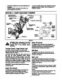
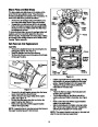
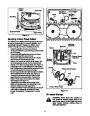
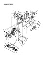
Raise the upper handle assembly until it locks over
the lower handle.
Look at the lower rear of snow thrower frame to be
sure both cables are aligned with cable roller
guides.
Unpacking
•
Secure the upper handle and lower handle with the
two plastic wing knobs, cupped washers and
carriage bolts previously removed and tighten the
upper two plastic wing nuts. See Figure 3.
•
Remove screws from the top sides and ends of the
shipping crate.
Set panel aside to avoid tire punctures or personal
injury.
•
•
•
Remove and discard plastic bag that covers unit.
Remove any loose parts included with unit (i.e.,
Operator’s Manual, etc).
Upper
Shift Rod
Shift Rod
Connector
•
Roll unit out of crate.
Loose Parts
Lower
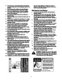
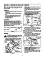
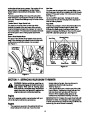
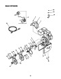
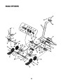
The augers are secured to the auger shaft with two
shear bolts and hex lock nuts. If you hit a foreign object
or ice jam, the snow thrower is designed so that the
bolts may shear. Two replacement shear bolts and nuts
are provided for your convenience. Store in a safe
place until needed. See Figure 1.
Shift Rod
Wing Nuts
Figure 3
Shear Bolts
Hex Lock
Nuts
•
Slide the shift rod connector down over the end of
the lower shift rod. Tap the connector until it locks
on the lower shift rod. See Figure 3.
NOTE: If the connector is not properly assembled, the
shift rod will pivot and you will not be able to change
speeds or change directions.
Figure 1
Assembly
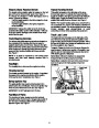
•
If not already attached, slip the cables that run from
the handle panel to the chute into the cable guide
located on top of the engine. See Figure 4.
WARNING: Disconnect the spark plug
wire and ground it against the engine to
prevent unintended starting.
Cable Guide
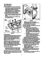
•
Remove the lower two plastic wing knobs, cupped
washers and carriage bolts from each side of the
lower handle. See Figure 2.
Lower
Handle
Handle
Panel
Figure 4
•
•
•
Unwrap the headlight wire, which is attached to the
headlight beneath the handle panel.
Wind the headlight wire around the right handle
until excess slack is removed.
Plug the wire from the headlight into the wire lead
coming from the right side of the engine, beneath
the fuel tank.
Upper Handle
Wing Nuts,
Washers, & Bolts
Figure 2
5
| Categories | MTD Snow Blower Manuals, Snow Blower Manuals, White Outdoor Snow Blower Manuals |
|---|---|
| Tags | MTD 31AH7Q3G190, MTD Snow Blower Manual, White Outdoor 31AH7Q3G190 |
| Download File |
|
| Document Type | Owner's Manual |
| Language | English |
| Product Brand | MTD, Snow Blower |
| Document File Type | |
| Publisher | mtdproducts.com |
| Wikipedia's Page | MTD Products |
| Copyright | Attribution Non-commercial |
(0 votes, average: 0 out of 5)