
1"
In-Line Electric Valve
Model 264
Installation Instructions
Introduction
The Toro 1" in-line electric valve is designed for use in automatic sprinkler systems controlled by a 24 VAC timer. The
valve features a manual bleed screw which enables the valve to be operated manually without the use of the timer. The
in-line valve has 1" male pipe threads for inlet and outlet fittings and is generally installed below grade grouped with
other valves in a manifold arrangement and housed in a protective valve box.
To ensure ease of installation and optimum valve performance, please read through the following instructions completely
before starting the installation procedure.
Note: A backflow prevention device installed upstream of the in-line valve(s) is required in most areas to prevent back-
siphoning of contaminants into the main water supply. The Toro 1" pressure vacuum breaker Model 220-14 is specifi-
cally designed for this purpose. Check with the proper municipal authority for information about building codes or
permits required for the installation of an underground sprinkler system.
Specifications
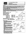
Figure 1
Operating Pressure Range: 20 – 150 PSI
Opening Time: 5 Seconds (max.)
24
Solenoid
VAC
Closing Time: 60 Seconds (max.)
Flow Range: 0.5 – 45.0 GPM
Friction Loss: @ 5 GPM - 2.0 PSI
@ 30 GPM - 5.4 PSI
@ 35 GPM - 7.0 PSI
@ 40 GPM - 8.7 PSI
@ 45 GPM - 10.5 PSI
@
@
@
@
10 GPM - 2.0 PSI
15 GPM - 2.3 PSI
20 GPM - 3.1 PSI
25 GPM - 4.0 PSI
Outlet
1"
Threads
NPT Male
Voltage Required: 24 VAC (nom.), 19 VAC (min.), 60 Hz
Solenoid Current Draw: Inrush - .25 Amps (max.) @ 24 VAC
Holding - .19 Amps (max.) @ 24 VAC
Inlet
Installation Procedure
1.
Flush valve supply line thoroughly to remove
all dirt and debris. This is very important!
Figure 2
2.
Wrap valve inlet threads with three to five layers
of Teflon™ tape.
To Sprinklers
Caution: Use only Teflon tape to seal
threads. Pipe dope will damage plastic
threads.
To Additional
Tee, Manifold
or Cap
3.
4.
See Figure 1 for inlet identification. Thread inlet
side of valve into a 1" slip/slip/thread tee fitting
tightening valve securely – do not tighten
excessively.
Using a short section of SCH 40 PVC, cement
required number of valve/tee assemblies together
to create a manifold. Connect manifold to 1" SCH
1"
Slip Fitting
Thread x
40
Figure 2.
PVC supply line using a 1" slip coupling. See
1"
Slip x
Note: Do not attach sprinkler lateral lines until
manifold assembly has been pressure tested for
leaks.
Slip x Thread
Fitting
5.
6.
Plug open end of manifold or connect 1" SCH 40
PVC pipe routed to another manifold assembly.
1" Supply Line
After allowing sufficient time for cement to cure,
apply water pressure to system. If no leakage
occurs, connect sprinkler lateral lines to valves.
| Categories | Sprinkler and Irrigation Manuals, Toro Sprinkler and Irrigation Manuals |
|---|---|
| Tags | Toro 264 |
| Download File |
|
| Language | English |
| Product Brand | Toro. Customer Service Representatives are available by phone:
Monday - Friday 7:30 a.m. to 9:00 p.m. (CDT) - Saturday 8:00 a.m. to 8:00 p.m. (CDT) - Sunday 10:00 a.m. to 8:00 p.m. (CDT)
Canada 1-888-225-4886 USA 1-888-384-9939 |
| Document File Type | |
| Publisher | toro.com |
| Wikipedia's Page | Toro Company |
| Copyright | Attribution Non-commercial |
(0 votes, average: 0 out of 5)