
220
Series Brass Valves
Bidding Specifications
(cont.)
Recommended
loss at 120 GPM shall not exceed
pressure gauge to verify downstream
pressure. The valve shall be able to field
retrofit with an optional pressure-
Installation Instructions
15.0
PSI on electric valves. For 2"
In commercial installations, it is
advantageous to mount valves in a valve
box. Logically, if mounted in valve
boxes, they can be located, accessed
and maintained easily. Instructions
should include the use of clean
models, friction loss at 180 GPM shall
not exceed 14.0 PSI on electric valves.
1
For 2⁄" models, friction loss at 250 GPM be factory or field installed. The
2
shall not exceed 7.0 PSI on electric
valves. For 3" models, friction loss at
regulating module, EZReg , which can
™
regulator shall be able to be field-
installed or serviced under pressure. The
valve shall have a forward-flow design
350
GPM shall not exceed 7.5 PSI on
aggregate to fill the bottom of the box,
and keeping valve box locations away
from structures, potential hardscaping
features (such as sidewalks) and large
planting locations. Additionally, valve
box locations generally should be in
shrub beds and at right angles to
structure locations. Valves can be
below grade but, even so, should
specify the use of 4" PVC pipe to the
valve bonnet and a Toro valve cover
(Part No. 850-00).
The pressure-regulating model gives
you a specifying choice in cases where
you must reduce a high available
pressure, where you are running
downhill or where you must isolate a
lateral at a lower pressure than the main
line. The pressure-regulating model
maintains a constant downstream
pressure, regardless of fluctuating
upstream pressure and flow conditions
through the valve.
Electric control valve instructions
should specify direct-burial wire,
utilizing different colors for hot hook-up
to each remote location and one color
for the common wire to all valves.
Watertight splice connections are
absolutely essential for proper valve
operation and should be covered with
in-depth instructions. Expansion loops
at each valve location on long-run wire
lengths generally are a good idea.
electric valves. The burst pressure safety to ensure more precise regulation when
rating shall be 750 PSI. The valve must
open or close in less than one minute at
used with a pressure regulator.
220
PSI, and less than 30 seconds at
Pressure Regulating Electric Models:
The pressure regulator, EZReg, shall
be of dial design to permit visual setting
of pressure with or without the valve
being operated or the use of a pressure
gauge. The regulator shall be of a
screw-in type and shall regulate
precisely over a 5-100 PSI range with
maximum inlet pressure of 220 PSI. The
regulator shall maintain the set pressure
within ± 3 PSI (with a 10 PSI differential
between inlet and outlet).
20
PSI.
The valve shall have a plastic
solenoid, which is fully encapsulated
and have a captured hex plunger and
spring. The solenoid will have a
removable retainer for servicing of the
spring and plunger. The plunger shall
be on a stainless-steel solenoid seat for
longer life. The 24 V a.c. solenoid shall
open with a 22.5 V a.c. minimum at
220
PSI. At 24 V a.c. average inrush,
current shall not exceed 0.40 amps.
Average holding current shall not
exceed 0.20 amps.
The [1"/1⁄"/1⁄"/2"/2⁄"/3"] 220 Series
4 2 2
1 1 1
valve shall be of [electric, electric
pressure regulating] configuration with
female-threaded inlet and outlet
connections. The 1"-2" valves shall be an
1
in-line configuration and the 2⁄"-3"
2
valves shall be an angle configuration.
The valve shall be developed,
manufactured, qualified and released in
the USA. The valve shall come with a
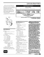
Line Pressure
Voltage
22.5
220
200
175
150
125
100
75
PSI
PSI
PSI
PSI
PSI
PSI
PSI
PSI
21.1
20.2
5-year
trade warranty.
19.1
18.2
The valve shall be manufactured,
qualified and released in the USA. The
valve, model number _______________,
shall be manufactured by The Toro
Company, Irrigation Division, El Paso,
Texas, USA.
17.1
16.1
50
16.0
The valve shall have a built-in,
Schrader-type valve for attaching a
Friction Loss
GPM Flow
Notes:
•
For optimum performance when
designing a system, be sure to calculate
total friction loss to ensure sufficient
downstream pressure.
Model
Electric
1"
5
10 15 20 30 40 50 60 70 80 100 120 150 170 180 200 250 300 350
•
For optimum regulation performance,
size regulating valves toward the higher
flow ranges.
2.0 2.5 1.5 2.5 5.5 7.0
1
1
⁄
4
"
5.5 6.5 7.5 8.0 8.5 9.0 13.0 16.0
1
1
⁄
2
"
4.0 5.2 5.4 6.0 6.5 7.0 8.0 10.0 15.0
1.0 2.0 2.0 2.5 3.0 3.5 6.0 7.5 10.0 12.0 14.0
2.0 2.2 2.3 2.4 2.5 3.0 4.0 4.5 5.5 7.0
2.2 2.4 2.5 3.0 4.0 4.5 5.5 6.5 7.0 7.5
2"
2⁄"
1
2
3"
SEPTEMBER 2000
- 2 of 2
- « Previous
- 1
- 2
| Categories | Sprinkler and Irrigation Manuals, Toro Sprinkler and Irrigation Manuals |
|---|---|
| Tags | Toro 220 Series |
| Download File |
|
| Language | English |
| Product Brand | Toro. Customer Service Representatives are available by phone:
Monday - Friday 7:30 a.m. to 9:00 p.m. (CDT) - Saturday 8:00 a.m. to 8:00 p.m. (CDT) - Sunday 10:00 a.m. to 8:00 p.m. (CDT)
Canada 1-888-225-4886 USA 1-888-384-9939 |
| Document File Type | |
| Publisher | toro.com |
| Wikipedia's Page | Toro Company |
| Copyright | Attribution Non-commercial |
(0 votes, average: 0 out of 5)