


Hydraulic Systems
3
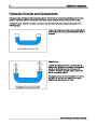
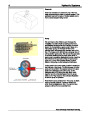
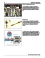
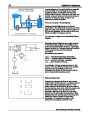
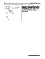
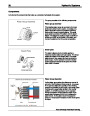
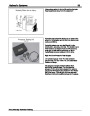
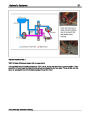
Hydraulic “Leverage”
If we take the concept discussed on the previous
slide and use containers or cylinders of different
sizes, we can increase the mechanical advantage to
lift a heavier load.
This is the principle that allows you to jack up a very
heavy object while exerting a small amount of force
on the handle of a hydraulic jack.
The animated illustration shows that 1 lb. of force
exerted on a 1 sq. in. piston, moved 10 in. will lift 10
lbs. a distance of 1 in. with a 10 sq. in. piston. Click
on the 'Play' button in the illustration to see a
demonstration. The larger piston will move a shorter
distance, but provides the mechanical advantage to
lift a much heavier load.
The mechanical workforce advantage in hydraulics
can be thought of as leverage, but it is hydraulic
leverage.
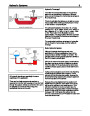
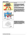
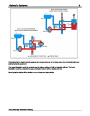
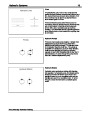
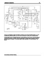
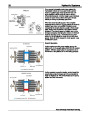
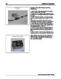
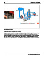
Basic Hydraulic System
Although hydraulic circuit layouts may vary
significantly in different applications, many of the
components are similar in design or function. The
principle behind most hydraulic systems is similar to
that of the basic hydraulic jack.
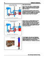
Oil from the reservoir is drawn past a check ball into
the piston type pump during the piston's up-stroke.
When the piston in the pump is pushed downward,
oil will be directed past a second check ball into the
cylinder.
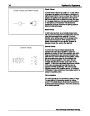
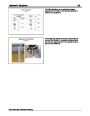
As the pump is actuated up and down, the incoming
oil will cause the cylinder ram to extend. The lift
cylinder will hold its extended position because the
check ball is being seated by the pressure against it
from the load side of the cylinder.
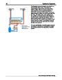
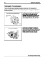
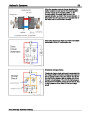
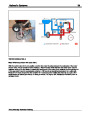
All hydraulic circuits are essentially the same
regardless of the application.
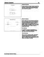
There are four basic components required; a
reservoir to hold the fluid; a pump to force the fluid
through the system; valves to control the flow; and
an actuator to convert the fluid energy into
mechanical force to do the work.
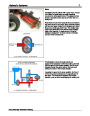
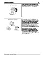
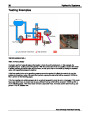
Because the pump displacement is usually much
smaller than the cylinder, each stroke of the pump
will move the cylinder a very small amount. If the
cylinder is required to move at a faster rate, the
surface area of the pump piston must be increased
and/or the rate which the pump is actuated must be
increased. Oil FLOW gives the cylinder ram its
SPEED of movement and oil PRESSURE is the work
force that lifts the load.
Toro University Technical Training
| Categories | Lawn Mower Manual, Sprinkler and Irrigation Manuals, Toro Sprinkler and Irrigation Manuals |
|---|---|
| Tags | Toro 09169SL |
| Download File |
|
| Document Type | Catalog |
| Language | English |
| Product Brand | Toro. Customer Service Representatives are available by phone:
Monday - Friday 7:30 a.m. to 9:00 p.m. (CDT) - Saturday 8:00 a.m. to 8:00 p.m. (CDT) - Sunday 10:00 a.m. to 8:00 p.m. (CDT)
Canada 1-888-225-4886 USA 1-888-384-9939, Lawn Mower |
| Document File Type | |
| Publisher | toro.com |
| Wikipedia's Page | Toro Company |
| Copyright | Attribution Non-commercial |
(1 votes, average: 3 out of 3)
Lawn and Garden readers have rated Toro Hydraulics Circuits Components Schematics Hydrostatic Drives Test Equipment 09169SL 3.0 out of 3.0 based on 1 product reviews. i am need information about circuit hydraulic of all machine