


ASSEMBLY
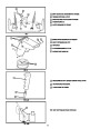
TO INSTALL THE CRANK ASSEMBLY
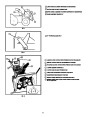
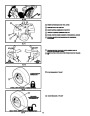
III.1 shows the snow thrower in the shipping position.
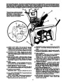
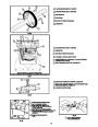
III.3 shows the snow thrower completely assembled.
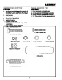
● On the right side of the handle, install the following
(
III.4:
found in parts box) in the lower hole as shown in
Reference to the right and left hand side of the snow
thrower is from the operator’s position at the handle.
1
- 3/8 x 2 inch bolt
TO REMOVE SNOW THROWER FROM
CARTON (See III.1)
2 - 3/8 inch flatwashers
1
1
- 3/8 inch lockwasher
- 3/8 inch nut
●
●
●
Remove top pallet from carton.
Locate and remove parts box.
●
Remove one 3/8" nylon locknut and flatwasher from
the “eye” bolt assembly (on the chute crank as-
sembly).
Cut all four corners of the carton from top to bottom
and lay the panels flat.
●
●
Cut the cable ties attached to the auger.
●
●
●
Install “eye” bolt through lower hole on the left hand
side of the handle. See III.4 for order of hardware.
Cut and discard the plastic ties that secure the crank
assembly and place the assembly aside.
Install the 3/8" flatwasher and the 3/8" nut loosely on
the “eye” bolt, as shown.
●
●
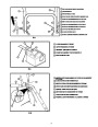
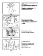
Remove the packing material from the control panel
and upper handle assembly.
Remove the plastic bag, plastic cap, cotter pin and
washer from the crank assembly and set aside (See
III.5).
Loosen (do not remove) both bolts securing the
upper and lower handles. Swing the upper handle
into the operating position.
●
●
●
Rotate the notched section of the discharge chute
toward the crank-adjusting rod (III.5).
●
Cut and discard the packing ties securing the clutch
cables to the lower handle.
Carefully remove cotter pin, clevis pin and drilled pin
from yoke end of crank rod assembly.
NOTE:If the cables have become disconnected from the
clutch levers, reinstall the cables as shown in III.2.
Place universal joint into end of worm gear lining up
largeholes. Insertdrilledpin(ensureopeninginpin
is in line with small openings in universal joint).
●
●
Tighten both bolts securely.
Roll the snow thrower off the skid by pulling on the
handle.
●
Place yoke end of crank rod around universal joint,
lining up openings. Insert clevis pin through assem-
bly and secure with cotter pin. Spread ends of cotter
pin to lock in place.
HOW TO SET UP YOUR SNOW
THROWER (See III.3)
TO SET THE SKID HEIGHT
●
●
Tighten the eye bolt installed earlier.
●
For packing, the height adjust skids were mounted
on the inside of auger housing with the bottom lip
turned inward and the mounting hardware on the
inside. Remove skid mounting nuts (III.3) and re-
mount on outside of auger housing with lip outward,
and mounting hardware to the outside as shown in
III.3.
Tightenthescrew,flatwasher,locknut,andhexnutat
the lower right hand hole (See III.4).
NOTE: Make sure the cables are not caught between the
upper and lower handle.
●
Rotate the chute crank fully clockwise and fully
counter-clockwise.
●
To adjust skid height for different conditions, refer to
the Service and Adjustment section.
IF YOU ARE REMOVING SNOW FROM
ANY ROCKY OR UNEVEN SURFACES,
RAISE THE FRONT OF THE SNOW
THROWER BY MOVING THE SKIDS
DOWN. THIS WILL HELP TO PREVENT
ROCKS AND OTHER DEBRIS FROM BE-
ING PICKED UP AND THROWN BY THE
AUGER.
17
| Categories | Husqvarna Snow Blower Manuals, Snow Blower Manuals |
|---|---|
| Tags | Husqvarna ST724 |
| Download File |
|
| Document Type | Owner's Manual |
| Language | English |
| Product Brand | Husqvarna, Snow Blower |
| Document File Type | |
| Publisher | husqvarna.com |
| Wikipedia's Page | Husqvarna |
| Copyright | Attribution Non-commercial |
(1 votes, average: 5 out of 5)
Lawn and Garden readers have rated Husqvarna ST724 Snow Blower Owners Manual 5.0 out of 5.0 based on 1 product reviews. Blower has been a great blower everytime I needed it Performed well