

SECTION 1: ASSEMBLING YOUR SNOW THROWER
Unpacking
•
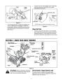
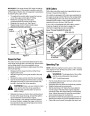
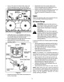
Secure the upper handle and lower handle with the
two plastic wing nuts, cupped washers and carriage
bolts previously removed. Attach these hardware
on the lower hole in the handles. See Figure 2.
Tighten the two wing nuts already in place on the
upper holes and secure the handles firmly. Slide
the shift rod connector down over the end of the
lower shift rod. Tap the connector until it locks over
the lower shift rod. See Figure 2.
•
Remove screws from the top sides and ends of the
shipping crate.
Set panel aside to avoid tire punctures or personal
injury.
Remove and discard plastic bag that covers unit.
Remove any loose parts included with unit (i.e.,
Operator’s Manual, etc.).
•
•
•
•
•
Roll unit out of crate.
NOTE: If the connector is not properly assembled, the
shift rod will pivot and you will not be able to change
speeds or direction of movement.
Loose Parts
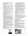
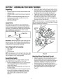
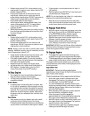
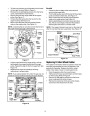
The augers are secured to the auger shaft with two
shear pins and cotter pins. If you hit a foreign object or
ice jam, the snow thrower is designed so that the pins
may shear. Two replacement shear pins and cotter pins
are provided for your convenience. Store in a safe
place until needed. See Figure 1.
Carriage
Bolt
Cupped
Washer
Shear Pins
Cotter
Pins
Shift Rod
Connector
Figure 1
Wing
IMPORTANT: NEVER replace the auger shear pins with
standard hex pins. Any damage to the auger gearbox or
other components from using standard pins will not be
covered by your snow thrower’s warranty.
Nuts
Hex
Nut
Items Required For Assembly
1.
2.
3.
Pair of pliers
Engine oil
Fresh gasoline
NOTE: All references in this manual to the left or right
side of the snow thrower is from the operating position
only. Exceptions, if any, will be specified.
Figure 2
Attaching Chute Directional Control
Assembling Handle
For shipping purposes, the upper handle is secured
loosely to the lower handle with four wing nuts.
•
Adjust the eyebolt on the chute directional control
so the rod does not come into contact with the
engine by moving the hex nut against the handle (if
necessary). Retighten the wing nut to secure the
directional control in this position.See Figure 2.
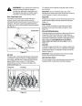
If not already attached, slip the cables that run from
the handle panel to the chute assembly into the
cable guide located on top of the engine. See
Figure 3.
•
Remove the lower plastic wing nut, cupped washer
and carriage bolt from each side of the lower
handle. See Figure 2.
•
•
•
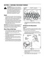
Raise the upper handle assembly until it locks over
the lower handle.
Look at the lower rear of the snow thrower frame to
be sure all the cables are aligned with the cable
roller guides. Make sure the spring (found at the
end of each cable) is attached to its actuator
bracket.
5
| Categories | Cub Cadet Snow Blower Manuals, MTD Snow Blower Manuals, Snow Blower Manuals |
|---|---|
| Tags | Cub Cadet 730 STE, MTD 730 STE, MTD Snow Blower Manual |
| Download File |
|
| Document Type | Owner's Manual |
| Language | English |
| Product Brand | MTD, Snow Blower |
| Document File Type | |
| Publisher | mtdproducts.com |
| Wikipedia's Page | MTD Products |
| Copyright | Attribution Non-commercial |
(0 votes, average: 0 out of 5)