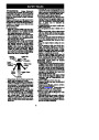
SAFETY NOTICE: Exposure to vibrations
through prolonged use of gasoline powered
hand tools could cause blood vessel or nerve
damage in the fingers, hands, and joints of
loss ofstrength,changeinskincolor ortexture,
or loss offeeling inthe fingers,hands, or joints,
discontinue the use of this tool and seek
medical attention. An anti-vibration system
does not guarantee the avoidance of these
problems. Users who operate power tools on
a continual and regular basis must monitor
closely their physical condition and the
condition of this tool.
people
prone to circulation disorders or
abnormal swellings. Prolonged use in cold
weather has been linked to blood vessel
damage
in
otherwise
healthy
people.
If
symptoms occur such as numbness, pain,
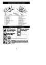
ASSEMBLY
Protective gloves (not provided) should be
worn during assembly.
begin mounting the bar onto the saw. See
illustration below.
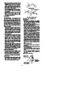
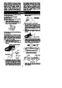
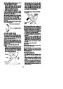
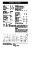
ATTACHING THE OPTIONAL
Inside view of
Chain Brake
BUMPER SPIKE
Theoptionalbumper spikemay beusedasa
pivot when making a cut.
1.
Loosenandremovethechainbrakenuts
and the chain brake from the saw.
Attach the bumper spike (optional) with
the two screws as illustrated.
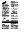
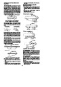
2.
Adjustment located on Chain Brake
Turn the adjusting screw by hand counter-
the adjusting pin just
4.
clockwise
until
touches the stop. This should allow thepin
to benear thecorrect position. Further ad-
justment may be necessary as you mount
the bar.
5.
6.
Slide guide bar behind clutch drum until
guide bar stops against clutch drum
sprocket.
ATTACHINGTHEBAR&CHAIN (Ifnot
already attached)
WARNING: If received assembled,
repeat all steps to ensure your saw is prop-
erly assembledand allfasteners aresecure.
Always wear gloves when handling the
chain. The chain is sharp and can cut you
even when it is not moving!
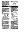
Mount the bar
Prepare the chain by checking the proper
direction. Without followingthe illustrationit
is easy toplacethechainon thesaw inthe
wrong direction. Use the illustration of the
chain to determine the proper direction.
1.
Loosenandremovethechainbrakenuts
and the chain brake from the saw.
Remove the plastic shipping spacer (if
present).
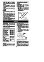
2.
Location of shipping spacer
Tip of
Bar
CUTTERS MUST FACE IN
DIRECTION OF ROTATION
Chain Brake
Nuts
Chain Brake
Cutters
Depth Gauge
Bar Tool
3.
An adjusting pin and screw is used to ad-
just the tension of the chain. It is very im-
portant when assembling the bar, that the
pin located on the adjusting screw aligns
intoaholein thebar. Turningthe screw will
move the adjustment pin up and down the
screw. Locate this adjustment before you
Drive Links
7.
Place the chain over and behind the
clutch, fitting the drive links in the clutch
drum sprocket.
6
| Categories | Chainsaw Manuals, Husqvarna Chainsaw Manuals |
|---|---|
| Tags | Husqvarna 137, Husqvarna 142 |
| Model Year | 2005 |
| Download File |
|
| Document Type | Operator's Manual |
| Language | English |
| Product Brand | Husqvarna, Chainsaw |
| Document File Type | |
| Publisher | husqvarna.com |
| Wikipedia's Page | Husqvarna |
| Copyright | Attribution Non-commercial |
(0 votes, average: 0 out of 5)