


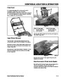
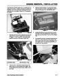


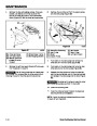


ELECTRIC START SYSTEM
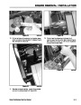
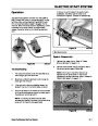
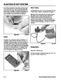
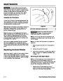
NOTE: When installing the wires, install the black
wires directly across from each other and the light
wires across from each other (Figure 68).
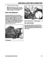
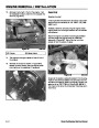
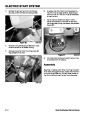
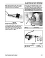
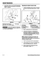
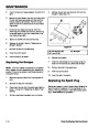
With the motor mounting screws removed, the motor
can be accessed from the top. To remove the pinion,
push the pinion stop down to uncover the wire lock ring
around the end of the armature (Figure 69). The lock
ring can be grasped with a pliers or side cutters and
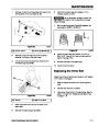
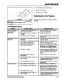
pulled off. Replace the ring; do not re-use. With the ring
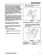
off the pinion and spring can be removed (Figure 70).
Figure 68
3428-0261
A
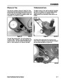
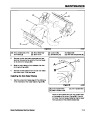
Starter Pinion Replacement
B
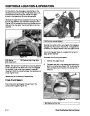
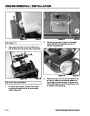
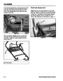
In order to replace the pinion, the upper shroud must
be removed and at least the two motor mounting
screws removed. If you know the wire, switch, and
motor are all ok, they can be left in place. Refer to
"System Disassembly" on page 5 - 1.
Figure 69
(B) Pinion Stop
3428-0264
(A) Ring
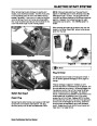
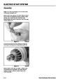
B C DE
A
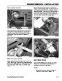
Figure 70
3428-0266
(A) & (B) Pinion Assembly
(C) Pinion Stop
(D) Spring
(E) Lock Ring
Snow Commander Service Manual
5 - 5
| Categories | Snow Blower Manuals, Toro Snow Blower |
|---|---|
| Tags | Toro Snow Commander |
| Model Year | 2005 |
| Download File |
|
| Language | English |
| Product Brand | Toro. Customer Service Representatives are available by phone:
Monday - Friday 7:30 a.m. to 9:00 p.m. (CDT) - Saturday 8:00 a.m. to 8:00 p.m. (CDT) - Sunday 10:00 a.m. to 8:00 p.m. (CDT)
Canada 1-888-225-4886 USA 1-888-384-9939, Snow Blower |
| Document File Type | |
| Publisher | toro.com |
| Wikipedia's Page | Toro Company |
| Copyright | Attribution Non-commercial |
(0 votes, average: 0 out of 5)