


SECTION 2: ASSEMBLING YOUR SNOW THROWER
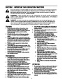
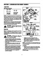
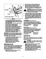
Loose Parts
Cupped
Washer
Auger Shear Bolts (Spares)
Carriage
Bolt
Upper
Handle
Hex Lock Nuts
5/16” Thread
(712-0429)
Shear Bolts
(710-0890A)
Wing
Nuts
NOTE: The augers are secured to the spiral shaft with
two shear bolts and hex lock nuts. If you hit a hard
foreign object or ice jam, the snow thrower is designed
so that the bolts may shear. Two replacement shear
bolts and nuts are provided for your convenience. Store
in a safe place until needed.
Lower
Handle
IMPORTANT: NEVER replace the auger shear bolts with
standard hex bolts. Any damage to the auger gearbox
or other components as a result of doing so will NOT be
covered by your snow thrower’s warranty.
Figure 1
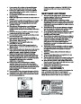
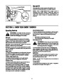
Upper
Shift Rod
WARNING: Disconnect spark plug wire
and ground it against the engine to prevent
unintended starting.
Shift Rod
Connector
Hex Nut
Assembly
Lower
Shift Rod
NOTE: All references to right or left side of the snow
thrower are determined from behind the unit in the
operating position. The “operator’s position” is defined
as standing directly behind the snow thrower, facing the
handle panel.
Eyebolt
WARNING: Disconnect the spark plug
wire and ground it against the engine to
prevent unintended starting.
Figure 2
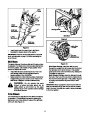
•
•
Retighten the wing nut to secure the chute
directional control in this position. See Figure 2.
Slide the shift rod connector down over the end of
the lower shift rod. Tap the top of connector until it
locks on the lower shift rod.
•
Remove the lower two plastic wing nuts, cupped
washers and carriage bolt (eyebolt on the left side)
from the lower handle. See Figure 1.
Raise the upper handle assembly until it aligns with
lower handle.
Be sure both cables are aligned with cable roller
guides located in the lower rear of snow thrower
frame.
•
•
NOTE: If the connector is not properly assembled, the
shift rod will pivot and you will not be able to shift gears
or change directions.
•
•
Secure the upper handle and lower handle with the
plastic wing nuts, cupped washers, and carriage
bolt (eyebolt on the left side) previously removed.
Adjust the eyebolt on the chute directional control
so the control rod does not come into contact with
the engine by moving the hex nut against the
handle (if necessary).
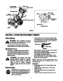
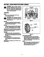
Lamp Wiring
•
Wrap the wire from the lamp down the right handle
until the wire can be plugged into the alternator lead
wire located under the fuel tank. See Figure 3.
IMPORTANT:Lamp wire must not interfere with any
controls or cables.
5
| Categories | MTD Snow Blower Manuals, Snow Blower Manuals |
|---|---|
| Tags | MTD 31AE640F352, MTD Snow Blower Manual |
| Download File |
|
| Document Type | Owner's Manual |
| Language | English |
| Product Brand | MTD, Snow Blower |
| Document File Type | |
| Publisher | mtdproducts.com |
| Wikipedia's Page | MTD Products |
| Copyright | Attribution Non-commercial |
(0 votes, average: 0 out of 5)