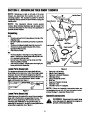


SECTION 3: ASSEMBLING YOUR SNOW THROWER
NOTE: References to right or left side of the snow
thrower are determined from behind the unit in the
operating position. The “operator’s position” is defined
as standing directly behind the snow thrower, facing the
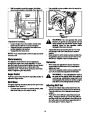
Handle Panel
handle panel.
Auger Control
NOTE: This Operator’s Manual covers several
models. Snow thrower features vary by model . Not
all features discussed in this manual are applicable to
all snow thrower models.
Traction Control
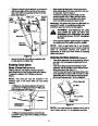
Unpacking
Crate
Right Clutch
Bracket
•
Remove screws from the top sides and ends of the
shipping crate.
Left Clutch
Bracket
•
Set panel aside to avoid tire punctures or personal
injury.
Shift Rod
Right Handle
•
•
Remove and discard plastic bag that covers unit.
Remove any loose parts included with unit (i.e.,
Operator’s Manual, etc).
Left Handle
•
Roll unit out of crate.
Box
•
Remove staples or break glue on top flaps of the
carton. Remove any loose parts included with unit
(i.e., operator’s manual, etc.).
Extension
Cord*
•
•
Cut corners of the carton and lay ends down flat.
Remove packing material.
Roll unit out of carton. Check carton thoroughly for
loose parts before discarding.
Discharge
Chute
Chute Directional
Control
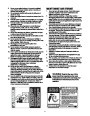
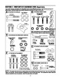
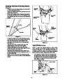
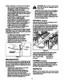
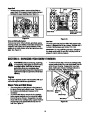
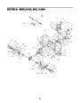
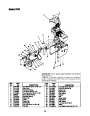
Loose Parts (Crated Unit)
Figure 2
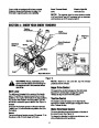
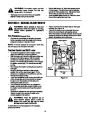
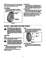
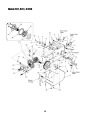
The augers are secured to the auger shaft with two
shear bolts and hex lock nuts. If you hit a foreign object
or ice jam, the snow thrower is designed so that the
bolts may shear. Two replacement shear bolts and nuts
are provided for your convenience. Store in a safe
place until needed. See Figure 1.
1. Right and Left Handles
2. Handle Panel Assembly
3. Right and Left Clutch Brackets
4. Discharge Chute
5. Chute Directional Control
6. Shift Rod
7.
8.
9.
Auger and Traction Controls
Hardware Pack
Extension Cord (*If Equipped)
Shear Bolts
Hex Lock
Nuts
NOTE: Follow the Assembly instructions below per
the packaging of your unit. So if your unit came in a box,
proceed to page 7, Assembly (Boxed Unit).
Figure 1
Loose Parts (Boxed Unit)
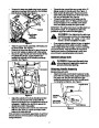
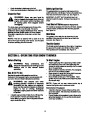
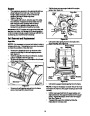
Assembly (Crated Unit)
Listed below are the parts of the snow thrower packed
loose with units that come unassembled in a box. You
will need these parts along with hardware from the
hardware pack, illustrated on the previous page, to
assemble the equipment. Identify the loose parts before
proceeding to assemble. See Figure 2.
WARNING: Disconnect the spark plug
wire and ground it against the engine to
prevent unintended starting.
6
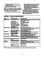
| Categories | MTD Snow Blower Manuals, Snow Blower Manuals |
|---|---|
| Tags | MTD 614E, MTD 644E, MTD 664G, MTD Snow Blower Manual |
| Download File |
|
| Document Type | Owner's Manual |
| Language | English |
| Product Brand | MTD, Snow Blower |
| Document File Type | |
| Publisher | mtdproducts.com |
| Wikipedia's Page | MTD Products |
| Copyright | Attribution Non-commercial |
(1 votes, average: 3 out of 3)
Lawn and Garden readers have rated MTD 614E 644E 664G Snow Blower Owners Manual 3.0 out of 3.0 based on 1 product reviews. Where is the carburator on the unit. Can I prime it to get it started?