


MAINTENANCE AND REPAIR INSTRUCTIONS
7.
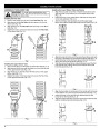
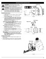
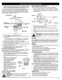
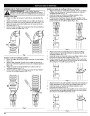
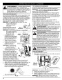
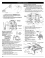
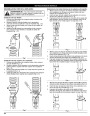
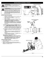
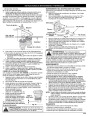
Slide the feeler gauge between the rocker arm and the valve return
spring. Measure the clearance between the valve stem and rocker
arm (Fig. 31). Measure both the intake and exhaust valves.
SPARK ARRESTOR MAINTENANCE
Inspect the spark arrestor after every 50 hours of operation.
1.
2.
Remove the rear engine cover. See Rocker Arm Clearance.
The recommended clearance for both intake and exhaust is .003 –
in. (.076 – 0.152 mm). Use a standard automotive .005 in.
mm) feeler gauge. The feeler gauge should slide between
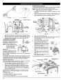
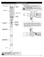
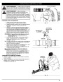
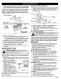
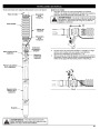
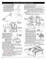
With a flat blade screwdriver or Torx T-20 bit and a T-25 bit,
remove the 4 screws attaching the spark arrestor cover to the
muffler (Fig. 34).
.006
(0.127
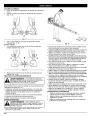
the rocker arm and valve stem with a slight amount of resistance,
without binding. See Figures 31 and 32.
Adjusting Nut
Rocker Arm
Muffler
T-25 Screws
T-20 Screw
Slot
Spark Arrestor Screen
.003–.006 in.
(.076–.152 mm)
Diverter
Fig. 34
3.
4.
Pull the tab on the spark arrestor cover out of the muffler.
Remove the spark arrestor cover.
Remove the spark arrestor screen from the spark arrestor
cover.
Clean the spark arrestor screen with a wire brush or replace it.
Reinstall the spark arrestor screen, spark arrestor cover and
screws.
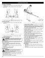
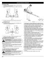
Intake Valve
Stem
Feeler Gauge
Valve Stem
5.
6.
Fig. 32
If the clearance is not within specification:
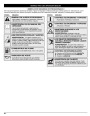
WARNING:
To avoid serious personal injury, always
turn your unit off and allow it to cool before you clean
or service it.
8.
9.
a. Turn the adjusting nut using a 5/16 inch (8 mm) wrench or nut
driver (Fig. 31).
CLEANING
•
•
To increase clearance, turn the adjusting nut counterclockwise.
To decrease clearance, turn the adjusting nut clockwise.
Use a small brush to clean off the outside of the unit. Do not use
strong detergents. Household cleaners that contain aromatic oils
such as pine and lemon, and solvents such as kerosene, can
damage plastic housing or handle. Wipe off any moisture with a
soft cloth.
b. Recheck both clearances, and adjust as necessary.
Reinstall the rocker arm cover using a new gasket. Torque the
screw to 20–30 in•lb (2.2–3.4 N•m).
10.
11.
12.
Check the spark plug and reinstall. See Replacing the Spark Plug.
Replace the spark plug wire.
Reinstall the engine cover. Check alignment of the cover
before tightening the screws. Tighten screws.
STORAGE
•
Never store the unit with fuel in the tank where fumes may reach
an open flame or spark.
•
Allow the engine to cool before storing.
REPLACING THE SPARK PLUG
• Lock up the unit to prevent unauthorized use or damage.
• Store the unit in a dry, well-ventilated area.
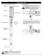
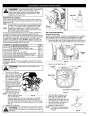
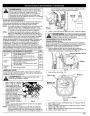
Use a replacement part number 753-05255 spark plug. The correct
air gap is 0.025 in. (0.635 mm.). Remove the plug after every 25
hours of operation and check its condition.
•
Store the unit out of the reach of children.
LONG TERM STORAGE
1.
Stop the engine and allow it to cool. Remove the eight (8)
1.
Drain all gasoline from the gas tank into a container. Do not
use gas that has been stored for more than 60 days. Dispose
of the old gasoline in accordance to Federal, State, and Local
regulations.
screws on the back of the engine cover with a Flat-head or T-
25
Torx screwdriver (Fig. 29).
2.
3.
Grasp the plug wire firmly and pull the cap from the spark
plug.
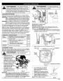
Clean dirt from around the spark
plug. Remove the spark plug
from the cylinder head by
turning a 5/8 in. socket
2.
3.
Start the engine and allow it to run until it stalls. This ensures
that all gasoline has been drained from the carburetor.
Allow the engine to cool. Remove the eight (8) screws on the
back of the engine cover with a Flat-head or T-25 Torx
screwdriver. Remove the spark plug and put 5 drops of high
quality motor oil into the cylinder. Pull the starter rope slowly
to distribute the oil. Reinstall the spark plug.
counterclockwise.
Replace cracked, fouled or dirty
spark plug. Set the air gap at
0.025
in.
4.
5.
(0.635
mm.)
NOTE: Remove the spark plug and drain all of the oil from the
cylinder before attempting to start the blower after storage.
0.025
in. (0.635 mm.) using a
feeler gauge (Fig. 33).
4.
5.
Change the oil, referring to Changing the Oil. Dispose of the
Install a correctly-gapped spark
plug in the cylinder head. Turn
the 5/8 in. socket clockwise
until snug.
old oil in accordance to Federal, State and Local regulations.
Thoroughly clean the unit and inspect for any loose or
damaged parts. Repair or replace damaged parts and tighten
loose screws, nuts or bolts. The unit is ready for storage.
Fig. 33
If using a torque wrench torque to:
in.•lb. (12.3-13.5 N•m)
Do not over tighten.
TRANSPORTING
110-120
•
•
•
•
Allow the engine to cool before transporting.
Secure the unit while transporting.
Drain the gas tank before transporting.
Tighten gas cap before transporting.
WARNING:
Do not sand blast, scrape or clean
electrodes. Grit in the engine could damage the
cylinder.
13
| Categories | Lawn Mower Manual, MTD Blower and Vacuum Manuals, MTD Lawn Mower Manuals, Troy-Bilt Blower and Vacuum Manuals, Troy-Bilt Lawn Mower Manuals |
|---|---|
| Tags | MTD TB4BP, Troy-Bilt TB4BP |
| Download File |
|
| Document Type | Owner's Manual |
| Language | English |
| Product Brand | MTD, Lawn Mower |
| Product Type | Walk Behind Mower |
| Document File Type | |
| Publisher | mtdproducts.com |
| Wikipedia's Page | MTD Products |
| Copyright | Attribution Non-commercial |
(0 votes, average: 0 out of 5)