


ENGLISH
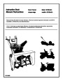
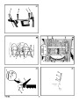
Traction Drive Lever (1) - Select the forward or 3. (Figure 2) To stop the engine, push the
throttle control lever (13) to off and remove
the ignition key (8).
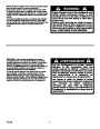
How To Start The Engine (Figure 2)
reverse direction of travel.
Models equipped with an Electric Starter
Crank Assembly (2) - Changes the direction of
the discharge chute.
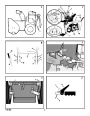
How To Go Forward or Backward
NOTE: An electric starter kit can be added to
recoil start engines. Electric starter kits are
available from your nearest authorized ser-
vice center.
(Figure 12)
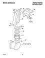
Discharge Chute (3) - Changes the distance the
1.
To change the ground speed, first release the
traction drive lever (1) and then move the
speed shift lever (6) to the desired speed.
snow is thrown.
WARNING: The starter is equipped
with a three- wire power cord and
plug and is designed to operate on
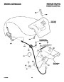
Remote Chute Control Lever (17) - Control the
distance the snow is thrown.
2.
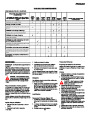
Ground speed is determined by snow condi-
tions. Select the speed by moving the speed
shift lever (6) into the appropriate notch on
the shift lever plate.
120 volt A.C. household current. The power
cord must be properly grounded at all times
to avoid the possibility of electrical shock
which can injure the operator. Carefully fol-
low all instructions in the “How To Start The
Engine” section. Make sure that your house
wiring is a three- wire grounded system. If
you are not sure, ask a licensed electrician.
If your house wire system is not a
three- wire grounded system, do not use
this electric starter under any conditions. If
your system is grounded but a three- hole
grounded receptacle is not available to start
the engine, have a three- hole grounded re-
ceptacle installed by a licensed electrician.
To connect a 120 volt A.C. power cord, al-
ways connect the power cord to the switch
box (11) on the engine first. Then, plug the
other end into the three- hole grounded re-
ceptacle. When disconnecting the power
cord, always unplug the end from the
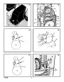
Auger Drive Lever (5) - Starts and stops the au-
ger and impeller (snow gathering and throwing).
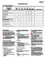
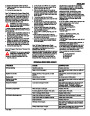
Speed 1, 2
Speed 3
Speed 4
Wet, Heavy
Light
Very Light
Transport only
Speed Shift Lever (6) - Selects the speed of the
snow thrower.
Speed 5, 6
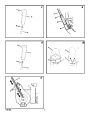
3.
To go forward, engage the traction drive
lever (1). Maintain a firm hold on the handle
as the snow thrower starts to move forward.
Guide the snow thrower by moving the han-
dle either left or right. Do not attempt to push
the snow thrower.
Height Adjust Skid (7) - Adjusts the ground
clearance of the auger housing.
Ignition Key (8) - Must be inserted to start the en-
gine.
4.
5.
To go backward, release the tractor drive
lever (1).
Move the speed shift lever (6) into either
Primer Button (9) - Injects fuel directly into the
carburetor for fast starts in cold weather.
first or second reverse.
Electric Start Button (10) - On electric start mod-
els, used to start the engine.
6. Engage the traction drive lever (1).
IMPORTANT: Do not move the speed shift
lever (6) while the traction drive lever (1) is
engaged.
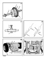
Switch Box (11) - On electric start models, used
to attach a 120 volt electric power cord.
three- hole grounded receptacle first.
Recoil Starter Handle (12) - Use to manually How To Throw Snow (Figure 12)
How To Start A Cold Engine (Figure 2)
start the engine.
1.
2.
Engage the auger drive lever (5).
To stop throwing snow, release the auger
drive lever (5).
1.
2.
Check the engine oil.
Fill the fuel tank with regular unleaded petrol.
See “How To Prepare The Engine”.
Make sure the traction drive lever (1) and
the auger drive lever (5) are in the disen-
gaged (released) position.
Throttle Control (13) - Controls the speed of the
engine.
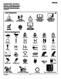
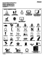
WARNING: The operation of any
snow thrower can result in foreign
objects being thrown into the eyes,
3.
4.
Choke Control (14) - Use to start a cold engine.
which can result in severe eye damage.
Always wear safety glasses or eye shields
while operating the snow thrower. We rec-
ommend standard safety glasses or use a
wide vision safety mask over your glasses.
Move the throttle control (13) to the fast
position.
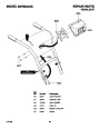
Shear Bolts (19) - To protect the machine, spe-
cial shear bolts are designed to break is an ob-
ject becomes lodged in the auger housing. The
use of a harder bolt will destroy the protection
provided by the shear bolt.
5. Insert the ignition key (8) into the ignition
slot. Make sure the ignition key (8) snaps
into place. Do not turn the ignition key (8).
Remove the extra ignition key and keep in a
safe place.
Drift Cutters (18) - (if equipped) Cuts a path Before Starting The Engine
through snow higher than the auger housing.
1.
Before you service or start the engine, famil-
6. Move the choke control (14) to the full
choke position.
iarize yourself with the snow thrower. Be
sure you understand the function and loca-
tion of all controls.
How To Control
The Discharge Of The Snow
7. (Electric Start) Connect the power cord to
the switch box (11) located on the engine.
8. (Electric Start) Plug the other end of the
power cord into a three-hole, grounded 120
VOLT, A.C. receptacle. (See the WARNING
in this section).
2.
Check the tension of the clutch cable before
starting the engine. See “How To Adjust The
Clutch Cable” in the Maintenance section of
this manual.
WARNING: Never direct the dis-
charge of snow toward bystanders.
3.
4.
Make sure that all fasteners are tight.
9. Push the primer button (9). Every time you
push the primer button (9), wait two sec-
onds. For the number of times required to
push the primer button (9), see the engine
manufacturer’s instructions.
WARNING: Always stop the engine
before unclogging the discharge
chute or the auger housing and be-
Make sure the height adjust skids are proper-
ly adjusted. See “How To Adjust The Height
Of The Skids” in the Maintenance section of
this manual.
fore leaving the snow thrower.
10.
(Electric Start) Push on the electric start
button (10) until the engine starts. Do not
crank for more than 10 seconds at a time.
The electric starter is thermally protected. If
the electric starter overheats, it will automati-
cally stop and can only be restarted when it
has cooled to a safe temperature. A wait of
about 5 to 10 minutes is required to allow the
electric starter to cool.
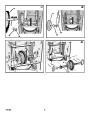
1.
2.
(Figure 2) Turn the crank assembly (2) to
change the discharge direction of the snow.
(Figure 12) Push the remote chute lever (2)
forward to discharge the snow high and far.
Pull the remote chute lever (2) back to dis-
charge the snow down.
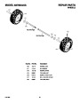
5. Check the air pressure in the tires. The cor-
rect air pressure is 14 PSI (1 BAR) to 17 PSI
(1.25 BAR). Do not exceed the maximum
amount of air pressure shown on the side of
the tire.
How To Stop The Engine (Figure 2)
How To Stop The Snow Thrower
(Figure 12) To stop discharging snow, re-
lease the auger drive lever (5).
To stop the wheels, release the traction
drive lever (1).
To stop the engine, move the throttle control
(3) to the stop position and remove the ignition
key (8). Keep the ignition key (8) in a safe
place. The engine will not start without the igni-
tion key (8).
1.
11. (Recoil Start) Rapidly pull the recoil starter
handle (12). Do not allow the recoil starter
handle (12) to snap back. Slowly return the
recoil starter handle (12).
2.
F-031088L
14
| Categories | Murray Snow Blower Manuals, Snow Blower Manuals |
|---|---|
| Tags | Murray 627804X5A |
| Download File |
|
| Document File Type | |
| Copyright | Attribution Non-commercial |
(1 votes, average: 5 out of 5)
Lawn and Garden readers have rated Murray 627804X5A Snow Blower Owners Manual 5.0 out of 5.0 based on 1 product reviews. This snow blower takes a lickin and keepsn tickin! It's easy to start and easy to operate. After the plows come through the snow blower cuts through the compacte3d snow like butter.