


Features & Controls
Control Functions continued…
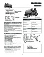
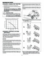
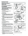
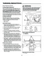
N. Cruise Control
The cruise control is used to set a constant FORWARD
ground speed. This is useful when mowing long rows or
traveling long distances.
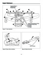
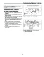
G. Ignition Switch
The ignition switch starts and stops the engine, it has
three positions:
To engage the cruise control, make certain forward area
is clear and slide the cruise control lever forward to the
desired ground speed. Move the lever fully back to the
NEUTRAL position to disengage. Note that in the event
you need to stop quickly, fully depressing the brake
pedal (I, Figure 1) will automatically release the cruise
control and stop the tractor. For normal operation, it is
recommended that you manually disengage the cruise
control by returning the lever to the NEUTRAL position.
OFF
Stops the engine and shuts off the
electrical system.
RUN
Allows the engine to run and powers the
electrical system.
START Cranks the engine for starting.
NOTE: Never leave the ignition switch in the RUN posi-
tion with the engine stopped–this drains the battery.
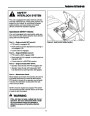
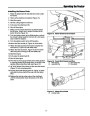
H. Front PTO Switch
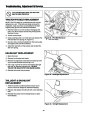
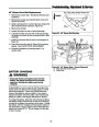
O. Two-Speed Control
The PTO (Power Take-Off) switch engages and disen-
gages attachments that use the front PTO. To engage
the PTO, pull UP on the switch. Push DOWN to disen-
gage. Note that the operator must be seated firmly in the
tractor seat for the PTO to function.
The two-speed control allows the operator to switch the
transmission into high-speed or low-speed, and to disen-
gage the transmission into a NEUTRAL (free-wheeling)
position.
Select the low-speed for heavy work (mowing,
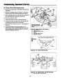
I. Parking Brake Knob
snowthrowing, etc), and high-speed for traveling to and
from work areas. DO NOT SHIFT WHILE MOVING.
The parking brake is applied by fully depressing the
brake pedal (J, Figure 1), and then pulling OUT on the
parking brake knob (I, Figure 1). To release the parking
brake, fully depress the brake pedal, and push the park-
ing brake knob IN.
To change gears:
1.
Stop the tractor, but DO NOT apply the parking brake
or depress the brake pedal.
2.
3.
4.
Lift UP on the shift knob.
Move the lever to the desired gear.
Push DOWN on the knob to lock into gear.
J. Brake Pedal
Depressing the brake pedal (I, Figure 1) returns the
transmission to neutral, and applies the tractor brake.
Note: If necessary, rocking the tractor back and forth
slightly makes shifting easier.
K. Ground Speed Control Pedals
The tractor’s ground speed is controlled by the ground
speed control pedals (J, Figure 1), and the cruise control
(see below).
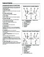
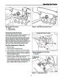
P. Differential Lock
The differential lock (H, Figure 1) can be used to
increase traction by locking the transmission differential
(for example when one of the rear wheels starts slip-
ping). To engage, DEPRESS the differential lock pedal
located at the rear of the left foot rest.
Depress the FRONT pedal to increase FORWARD
ground speed.
Depress the REAR pedal to increase REVERSE ground
speed. Note that the further down the pedals are
depressed, the faster the tractor will travel.
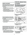
Q. Attachment Lift Pedals
The attachment lift pedals (G, Figure 1) raise and lower
attachments such as mower decks, snowthrowers, and
tillers.
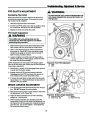
L. Steering Wheel Adjustment
The tractor is equipped with a tilt steering wheel. Push
DOWN on the tilt adjust tab located on the rear of the
To RAISE an attachment, depress the REAR attachment
lift pedal until the desired position is achieved.
steering column, and tilt the steering wheel to the desired Releasing the pedal holds the lift cylinder in position.
position.
Depressing and releasing the FRONT pedal lowers the
M. Seat Adjustment Lever
attachment lift cylinder and holds it in position.
Depressing the pedal beyond the detent locks it in
FLOAT position. In FLOAT mode the attachment can
float through the full range of the lift cylinder.
The seat can be adjusted forward and back. Move the
lever to the LEFT, position the seat as desired, and
release the lever to lock the seat into position.
R. Auxiliary Hydraulic Control Levers
(Optional)
The auxiliary hydraulic control levers control the flow of
hydraulic oil to the quick connectors located under the
left footrest. See pages 14-15 for specific operating
information on the auxiliary hydraulic system.
9
(0 votes, average: 0 out of 5)