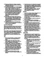
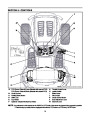


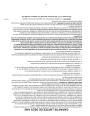


SECTION 4: TRACTOR SET-UP
NOTE: Reference to RIGHT or LEFT side of the
tractor in this manual is observed from operator’s
position.
WARNING: Do NOT operate the tractor
without first attaching both the steering
wheel AND the seat. Doing so could result
in serious injury to the operator.
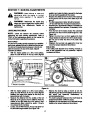
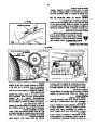
ATTACHING THE BATTERY CABLES
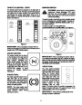
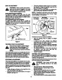
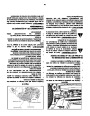
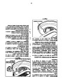
NOTE: There are two different styles of steering
wheel cap. See Figure 2. Styles vary by model.
NOTE: The battery cables may or may not be
attached on your unit. If the cables are not attached,
please follow the instructions below.
•
•
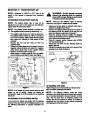
Using your hands, place the tractor’s front tires in
position for straight-ahead travel.
NOTE: The positive battery terminal is marked Pos.
(+). The negative battery terminal is marked Neg. (–).
Remove the steering wheel cap from the center of
the steering wheel. Be careful not to lose the hex
screw and cupped washer found beneath it.
Place the steering wheel (in position for straight-
ahead travel) directly onto the steering shaft found
in the center of the tractor’s dash.
Place the cupped washer (cupped side DOWN)
over the steering shaft.
Thread the hex screw into the steering shaft and
tighten securely.
•
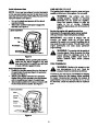
The positive cable (heavy red wire) is secured to
the positive battery terminal (+) with a hex bolt and
hex nut at the factory. Make certain that the rubber
boot covers the terminal to help protect it from
corrosion.
•
•
•
•
•
•
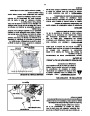
Remove the hex bolt and wing nut from the
negative cable.
Remove the black plastic cover, if present, from the
negative battery terminal and attach the negative
cable (heavy black wire) to the negative battery
terminal (–) with the bolt and wing nut.
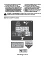
Reinsert the steering wheel cap in the center of the
steering wheel. Refer to Figure 2.
Steering
Wheel Cap
•
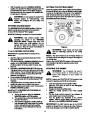
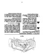
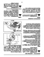
Make certain the battery retainer rod is in position
over the battery, securing it in place. See Figure 1.
Hex Bolt
& Washer
Rubber
Boot
Battery
Positive
Terminal
Steering
Shaft
Wing
Nut
Negative
Terminal
Battery
Retainer Rod
Figure 2
Shoulder Bolt
Figure 1
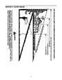
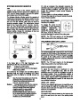
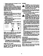
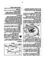
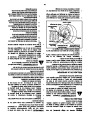
ATTACHING THE SEAT
Refer to Figures 3 and 4 to identify your tractor’s seat
style and follow applicable instructions.
NOTE: If the battery is put into service after the date
shown on top of battery, charge the battery as
instructed on page 22 of this manual prior to operating
the tractor.
NOTE: For shipping reasons, seats are either
fastened to the tractor seat’s pivot bracket with a plastic
tie, or mounted backward to the pivot bracket. In either
case, free the seat from its shipping position and
remove the two hex screws (or knobs, on models so
equipped) from the bottom of seat before proceeding
with applicable instructions below.
ATTACHING THE STEERING WHEEL
In the event your tractor was crated with the steering
wheel and the seat removed for shipping reasons, use
the following instructions to properly assemble the
parts.
8
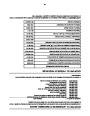
| Categories | Lawn Mower Manual, MTD Lawn Mower Manuals, Yard Machines Lawn Mower Manuals |
|---|---|
| Download File |
|
| Document Type | Owner's Manual |
| Language | English |
| Product Brand | MTD, Lawn Mower |
| Product Type | Walk Behind Mower |
| Document File Type | |
| Publisher | mtdproducts.com |
| Wikipedia's Page | MTD Products |
| Copyright | Attribution Non-commercial |
(0 votes, average: 0 out of 5)