


3
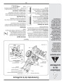
Setting Up
Your Snow
Thrower
Figure 3-4
Figure 3-5
•
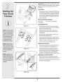
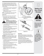
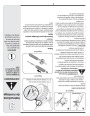
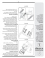
Slide chute assembly over chute opening, making
sure the flange keepers are beneath lip of chute
adapter. The notches should engage with the spiral
end of the chute crank. See Figure 3-5.
WARNING
Prior to operating
your snow thrower,
refer to Auger Control
on page 9. Read and
follow all instructions
carefully and perform
all adjustments to
verify your unit is
operating safely and
properly.
•
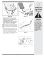
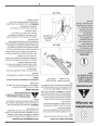
Secure flange keeper, locknuts and screws previously
removed. Tighten all flange keepers and hardware
with two 7/16” wrenches. Do not over tighten.
NOTE: If necessary the chute crank support bracket can
be adjusted so the spiral on the chute crank fully engages
the teeth on the chute assembly. Refer to the Adjustment
Section.
•
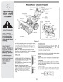
If not already attached, slip the cables that run from
the handle panel to the discharge chute into the cable
guide located on top of the engine. See Figure 3-6.
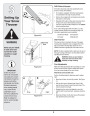
•
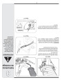
Wrap the wire from the head lamp down the right
handle until the wire can be plugged into the alternator
lead wire under the fuel tank. See Figure 3-7.
Figure 3-6
Alternator Lead
Alternator
Lead
Lamp Wire
NOTE: Wheels are omitted from illustration for clarity.
Figure 3-7
7
| Categories | MTD Snow Blower Manuals, Snow Blower Manuals, Yard Man Snow Blower Manuals |
|---|---|
| Tags | MTD 769-04095, MTD Snow Blower Manual, Yard Man 769-04095 |
| Download File |
|
| Document Type | Owner's Manual |
| Language | English |
| Product Brand | Yard-Man, 769-04095, Snow Blower |
| Document File Type | |
| Publisher | mtdproducts.com |
| Wikipedia's Page | MTD Products |
| Copyright | Attribution Non-commercial |
(0 votes, average: 0 out of 5)