
SECTION 9 - CHUTE CRANK KIT
9.1
CHUTE CRANK KIT
Instructions
1.
Remove cowl from unit by loosening 8 screws at
lower front sides. Remove two screws at rear
corners and remove fuel cap. After removing cowl,
replace fuel cap to avoid spills and fumes.
(for use on models 938010, 015, 016, 305)
WARNING: FAILURE TO FOLLOW
INSTRUCTIONS could result in personal
injury and/or damage to unit.
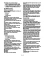
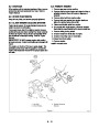
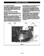
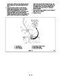
2. Install flange bushing in discharge chute rotation
bracket with flange toward centerline of chute.
Then hold the 18 tooth chute pinion in place in front
of the bushing by rolling it in place in mesh with the
chute gear. The identification marks on pinion and
gear must line up with each other, see Figure 15.
Read, understand, and follow all safety
practices in Owner/Operator Manual before
beginning.
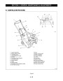
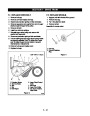
View alignment marks through this slot.
7
6
8
1
2
3
4
5
1
1.
2.
3.
4.
Pinion-Discharge Chute 18 T
Flange Bushing
Crank Pinion 12 T
5. Internal Hair Pin
6. Chute Assembly Crank
7. Knob
Chute Crank Shaft
8. Crank Gear 48 T
Figure 15
OS1650
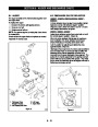
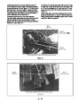
3.
4.
Install the 12 tooth pinion on the transfer shaft so
that the drive tang/stops are seated in the notches
in the pinion. Insert the shaft through the hole in
the chassis, through the flange bushing and finally
through the 18 tooth chute pinion. Align the hole in
the shaft with the holes in the pinion. Install the
small hair pin through the holes so that it seals
over the hub of the pinion.
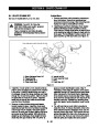
space and tooth identification marks. Align if
necessary. Insert cotter pin (taped to chute crank
assembly) through 48T gear and chute crank shaft.
Minor movement of the crank Shaft or discharge
chute handle may be needed to align holes. Rotate
chute crank to access cotter pin and secure pin by
bending ends over. Reinstall nut, securing chute
crank and starter handle brackets to lower handle
bar.
Remove nut from bolt that holds recoil starter
Handle bracket in place. Install the chute crank
assembly beneath the lower handlebar by starting
end through hole in chassis. Hold crank spacer
and then 48 tooth gear in place, sliding only as far
as needed to get them started. With crank knob
straight up and discharge chute straight forward,
check that 48T gear meshed with 12T pinion at
5. You will note that too much effort is required to
rotate the chute. To reduce that effort, remove the
three bolts that hold the discharge chute onto the
ring and remove the chute. Then remove the four
screws that attach the ring to the chute gear, and
remove the ring. Now you can remove the detent
ball and spring and replace the above parts in
9
- 20
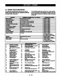
| Categories | Ariens Snow Blower Manuals, Snow Blower Manuals |
|---|---|
| Tags | Ariens 938001, Ariens 938004, Ariens 938006, Ariens 938012, Ariens 938015, Ariens 938016, Ariens 938301, Ariens 938305 |
| Download File |
|
| Document Type | Service Manual |
| Language | English |
| Product Brand | Ariens, Snow Blower |
| Document File Type | |
| Publisher | ariens.com |
| Wikipedia's Page | Ariens |
| Copyright | Attribution Non-commercial |
(0 votes, average: 0 out of 5)