


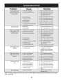

SERVICE & ADJUSTMENTS
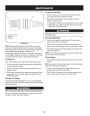
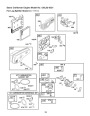
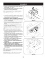
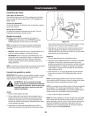
FLexibLe PUMP COUPLeR
The flexible pump coupler is a nylon “spider” insert, located between
the pump and the engine shaft. Over time, the coupler will harden and
deteriorate.
Replace the coupler if you detect vibration or noise coming from the
area between the engine and the pump. If the coupler fails completely,
you will experience a loss of power.
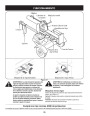
IMPORTANT: Never hit the engine shaft in any manner, as a blow will
cause permanent damage to the engine.
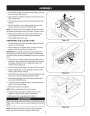
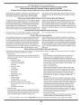
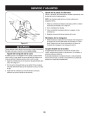
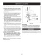
Set Screw
1.
Remove three nuts that secure the pump to the coupling shield.
Two nuts are at the bottom corners and one is in the top center.
See Figure 5-2.
Side View-Coupler
2.
3.
Remove the pump.
.0600
.0100
Rotate the engine by slowly pulling starter handle until engine
coupling half set screw is visible. Loosen set screw using allen
wrench and slide coupling half off engine shaft.
Loosen set screw on pump coupling half and remove coupling half.
Slide new engine coupling half onto the engine shaft until the end of
the shaft is flush with the inner portion of the coupling half. (There
must be space between the end of the engine support bracket and
coupling half). Tighten set screw.
Install pump coupling half and key on pump shaft. Rotate coupling
half until set screw faces opening in shield. Do not tighten set
screw.
Install nylon “spider” onto engine coupling half.
Align pump coupling half with nylon “spider” by rotating engine
using starter handle. Slide coupling half into place while guiding
three mounting bolts through holes in pump support bracket.
Secure with nuts removed earlier.
4.
5.
Figure -
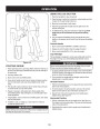
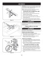
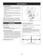
t iReS
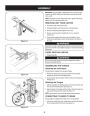
See sidewall of tire for recommended pressure. Under any circum-
stances do not exceed manufacturer’s recommended psi. Maintain
equal pressure on all tires.
6.
WaRninG
Excessive pressure when seating beads may cause tire/rim assembly
to burst with force sufficient to cause serious injury. Refer to sidewall
of tire for recommended pressure.
7.
8.
9.
10.
Set.010” to.060” clearance/gap between the nylon “spider” and
the engine coupling half by sliding a feeler gauge or matchbook
cover between the nylon “spider” and the engine coupling half and
moving pump coupling half as needed. Secure pump coupling half
with set screw. See Figure 5-2.
NOTEing set:screw.Make certain proper clearance/gap is obtained before tighten-
1
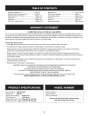
| Categories | Craftsman Lawn Mower Manuals, Lawn Mower Manual |
|---|---|
| Tags | Craftsman 247.77614, Craftsman 675 |
| Download File |
|
| Document Type | Operator's Manual |
| Language | English |
| Product Brand | Craftsman. Customer Service Representatives are available by phone: Canada 1-888-225-4886 USA 1-888-384-9939, Lawn Mower |
| Document File Type | |
| Publisher | craftsman.com |
| Wikipedia's Page | Craftsman (tools) |
| Copyright | Attribution Non-commercial |
(0 votes, average: 0 out of 5)