


6
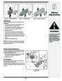
Maintaining
Your Snow
Thrower
Friction Wheel Removal
If the snow thrower fails to drive with the drive control
engaged, and performing the drive control cable adjust-
ment on page 12 fails to correct the problem, the friction
wheel may need to be replaced. Follow the instructions
below. Examine the friction wheel for signs of wear or
cracking and replace if necessary.
•
•
Place the shift lever in third Forward (F3) position.
Drainpiece theof plasticgasolineunderfromthethegassnowcap.thrower, or place a
•
Carefully pivot the snow thrower up and forward so
that it rests on the auger housing.
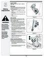
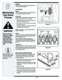
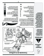
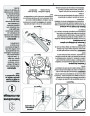
1.
a. Remove the frame cover from the underside of
the snow thrower by removing four self-tapping
screws which secure it. See Figure 6-13.
b. Remove the right-hand wheel by removing the
screw and cupped washer which secure it to the
axle.
Figure 6-13
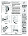
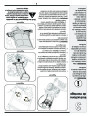
2.
3.
Carefully remove the hex nut and washer which
secures the hex shaft to the snow thrower frame and
lightly tap the shaft’s end to dislodge the ball bearing
from the right side of the frame. See Figure 6-14.
When reassembling
the friction wheel as-
sembly, tighten each
screw only one rota-
tion before turning the
wheel clockwise and
proceeding with the
next screw. Repeat
this process several
times to ensure the
plates are secured
with equal force.
Carefully position the hex shaft downward and to
the left before carefully sliding the friction wheel
assembly off the shaft. See Figure 6-15.
NOTE: If you’re replacing the friction wheel assembly
as a whole, discard the worn part and slide the new part
onto the hex shaft. Follow the steps above in reverse
order to reassemble components. If you’re disassem-
bling the friction wheel and replacing only the rubber
ring, proceed as follows:
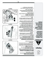
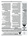
4.
Remove the four screws which secure the friction
wheel’s side plates together. See Figure 6-16.
•
•
•
Remove the rubber ring from between the plates.
Reassemble the side plates with a new rubber ring.
Slide the friction wheel assembly back onto the hex
shaft and follow the steps above in reverse order to
reassemble components.
Figure 6-14
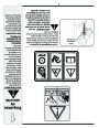
NEVER replace the
auger shear pins with
standard hex pins.
Any damage to the
auger gearbox or
other components
as a result of failing
to do so will NOT be
covered by your snow
thrower’s warranty.
Figure 6-1
Figure 6-16
1
| Categories | MTD Snow Blower Manuals, Snow Blower Manuals |
|---|---|
| Tags | MTD 769-03244, MTD Snow Blower Manual |
| Download File |
|
| Document Type | Owner's Manual |
| Language | English |
| Product Brand | MTD, Snow Blower |
| Document File Type | |
| Publisher | mtdproducts.com |
| Wikipedia's Page | MTD Products |
| Copyright | Attribution Non-commercial |
(0 votes, average: 0 out of 5)