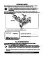
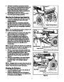
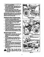
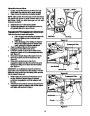

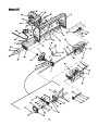
Routing the Lower Drive Belt
1.
Loosen, but do NOT remove the flange nut which
secures the belt keeper to the drive mounting
bracket. See Figure 16.
2.
Make sure that the “V” side of the lower drive belt is
seated firmly in the lower portion of the double
pulley found in the rear of the undercarriage
assembly.
Flange Nut
Drive Mounting
Bracket
3.
Route the opposite end of the lower drive belt
around the snow thrower’s drive pulley, to the
INSIDE of the belt keeper loosened in Step 1.
NOTE: Having a second person carefully pivot the
double-idler pulley mounted beneath the undercarriage
toward the left side of the tractor will relieve tension on
the lower drive belt and ease in routing it around the
drive pulley.
NOTE: View shown is from above the tractor.
4.
Retighten the flange nut loosened in Step 1 to
secure the belt keeper.
Figure 16
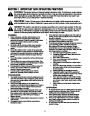
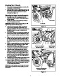
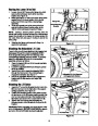
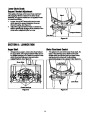
Attaching the Adjustable Lift Link
Power to the snow thrower attachment is engaged and
disengaged through the tractor’s adjustable lift link
found suspending through the front left area of the
undercarriage assembly mounted earlier. To properly
attach the adjustable lift link to the undercarriage
assembly, proceed as follows:
1.
2.
3.
Place the tractor’s lift lever in the lowest reachable
engagement notch.
Locate the adjustable lift link and thread it upward
as far as possible.
Insert the end of the tractor’s adjustable lift link
through the hole found in the undercarriage’s
engagement bracket. See Figure 17 .
Secure the adjustable lift link to the engagement
bracket with the flat washer and hairpin clip
provided.
Adjustable Lift Link Secured
to Engagement Bracket
4.
Figure 17
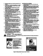
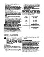
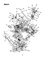
Attaching the Lift Cable
1.
Insert the “Z” end of the lift cable into the hole in the
lift index rod found on the right side of the support
carriage assembly. See Figure 18 .
2.
Position the threaded portion of the cable end into
the slot found on the lift bracket making certain that
one hex nut is above the lip of the bracket and the
flat washer and second hex nut are below the lip.
Tighten both hex nuts to securely fasten the
threaded portion of the lift cable to the lip of the lift
bracket.
Hex Nuts
3.
Lift Cable
‘Z’ End
IMPORTANT: Before operating your snow thrower, refer
to the Lift Adjustment in SECTION 7: ADJUSTMENTS to assure
your snow thrower’s lift cable is properly adjusted.
Lift Index Rod
Figure 18
10
| Categories | MTD Snow Blower Manuals, Snow Blower Manuals |
|---|---|
| Tags | MTD 190-627, MTD Snow Blower Manual |
| Download File |
|
| Document Type | Owner's Manual |
| Language | English |
| Product Brand | MTD, Snow Blower |
| Document File Type | |
| Publisher | mtdproducts.com |
| Wikipedia's Page | MTD Products |
| Copyright | Attribution Non-commercial |
(0 votes, average: 0 out of 5)