
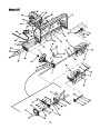
SECTION 4: ASSEMBLY
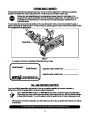
WARNING: Before installing attachment,
place tractor on a firm and level surface. Place
the PTO in the disengaged (OFF) position, set
the parking brake, shut engine off and remove
key to prevent unintended starting.
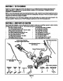
NOTE: Your tractor’s cutting deck and PTO belt must
be removed prior to mounting the snow thrower
attachment. Refer to your tractor’s Operator’s Manual
for detailed instructions. Retain all the deck hardware
and store it in a safe place. If your tractor is equipped
with any front-end accessory such as a front bumper
kit, it must also be removed.
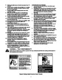
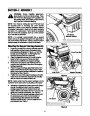
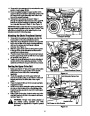
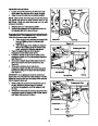
Hex Screw,
Belleville Washer
NOTE: It is strongly recommended that a second
person act as an assistant throughout the assembly of
the snow thrower attachment. Having a second person
present eases the completion of many of the steps.
NOTE: The lock washer and hex nut
are on the INSIDE of the pivot bracket.
Figure 4
Mounting the Support Carriage Assembly
1.
Fasten the provided hex screws, belleville washers,
lock washers and lock nuts to the tractor’s front
pivot bracket as illustrated in Figure 4 on both the
left side and the right side. Do NOT tighten the
hardware at this point in the assembly.
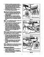
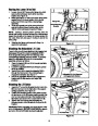
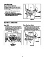
Front Pivot Bar
2.
3.
4.
Place the tractors front tires on 2x4s to bring the
tractor’s front end up a few inches and allow
clearance for positioning the support carriage.
Remove the hex screws, lock washers and hex
nuts from the both sides of the rear of the support
carriage assembly.
Place the support carriage assembly between the
tractor’s front tires so that the large notch on both
sides of the support carriage straddles the tractor’s
front pivot bar. See Figure 5.
Large Notch
Support Carriage
5.
Position the rear of the support carriage so that the
holes where the hardware was just removed align
with the holes in the tractor’s frame rail.
Figure 5
NOTE: Make certain that the support carriage is to the
OUTSIDE of the frame rail on both sides of the tractor.
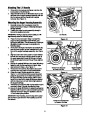
6.
Reinsert the rearmost hex screw removed in Step 3
through the aligning holes in both the support
carriage assembly and the tractor’s frame rail.
Fasten with the lock washer and hex nut but do not
tighten the hardware at this time. See Figure 6.
Pivot the front of the support carriage upward until
the small grooves found in the front portion of
support carriage slide between the belleville
washers inserted in step 1 and the tractor’s front
pivot bracket. See Figure 7.
7.
Hex Screw
NOTE: The lock washer and hex nut are
on the INSIDE of the tractor’s frame rail.
Figure 6
6
| Categories | MTD Snow Blower Manuals, Snow Blower Manuals |
|---|---|
| Tags | MTD 190-627, MTD Snow Blower Manual |
| Download File |
|
| Document Type | Owner's Manual |
| Language | English |
| Product Brand | MTD, Snow Blower |
| Document File Type | |
| Publisher | mtdproducts.com |
| Wikipedia's Page | MTD Products |
| Copyright | Attribution Non-commercial |
(0 votes, average: 0 out of 5)