


3
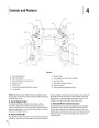
Assembly & Set-Up
Contents of Crate
•
•
One Lawn Tractor
•
•
One Oil Drain Tube
•
•
One Deck Wash Hose Coupler
One Product Registration Card
One RZT Tractor Operator’s
Manual
One Briggs & Stratton Engine
Operator’s Manual
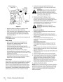
TRACTOR PREPARATION
Remove the upper crating material from the shipping
pallet, and cut any bands or tie straps securing the tractor
to the pallet.
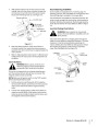
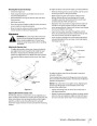
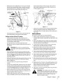
4. Align the grooves in the seat adjust spacers with the
sides of the adjustment slots in the pivot bracket.
5
.
Slide the seat adjust spacers into the slots of the pivot
bracket.
6
.
Continue to push the seat forward in the pivot bracket
until the front/left shoulder bolt of the seat assembly
passes forward of the stop bracket on the seat pivot
bracket. See Figure 3-2.
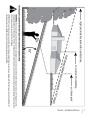
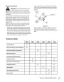
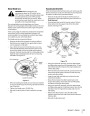
Use the lift handle to raise the deck to its highest position.
Engage the transmission bypass rods on each side of the
tractor; then carefully roll the tractor off the shipping
pallet. Disengage the bypass rods. See Figure 3-1.
RH Transmission
Bypass Rod
Pull Out
Adjustment
Slots
Bypass Rod
Seat
Seat
Then Lower
In Slot
Pivot
Bracket
Seat
Adjust
Spacer
Keyhole
Slot
Front/Left
Shoulder Bolt
Seat Adjust
Lever
Figure 3-1
Stop Bracket
Remove the deck wash system nozzle adapter from the
manual bag and store for future use.
Figure 3-2
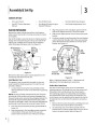
Install Operator’s Seat
Refer to “Adjusting Operator’s Seat” in Maintenance &
The operator’s seat was partially inserted into the seat
pivot bracket for shipping purposes. To install the seat
proceed as follows:
Adjustments for seat adjustment instructions.
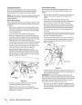
Position Drive Control levers
1
.
Cut any straps securing the seat assembly and the
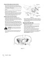
The drive control levers of the tractor are lowered for
drive control levers to the tractor. Remove any packing shipping purposes. The flange lock nuts, hex screws, and
material.
flat washers that normally secure the control levers in
their operating position are unfastened and installed in
the slotted holes of the control levers for shipment. The
control levers must be repositioned to operate the tractor.
To reposition the control levers for operation, proceed as
follows:
NOTE: The seat is partially inserted into the slots of the seat
pivot bracket. If the seat does not become disengaged from
the pivot bracket when removing the packaging material, the
pivot bracket may be pivoted upward and the seat pushed
into place as described in step 6. If the seat does disengage the
pivot bracket, install the seat as instructed in steps 2 thru 6.
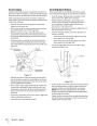
1. Remove the hex screw, flat washer, and flange lock nut
from the slot of one of the drive control levers.
2
.
Pivot the seat pivot bracket partially upward. Refer to
Figure 3-2.
2
.
Lift and swing that control lever upward until the
slotted hole in the lever bracket aligns with one of the
holes in the pivot bracket. Refer to Figure 3-3.
3
.
Note the grooves in the seat adjust spacers attached
to the bottom of the seat, then lift the seat and
position above and to the rear of the pivot bracket.
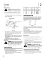
| Categories | Lawn Mower Manual, MTD Lawn Mower Manuals, Troy-Bilt Lawn Mower Manuals |
|---|---|
| Tags | MTD RZT, Troy-Bilt RZT |
| Download File |
|
| Document Type | Owner's Manual |
| Language | English |
| Product Brand | MTD, Lawn Mower |
| Document File Type | |
| Publisher | mtdproducts.com |
| Wikipedia's Page | MTD Products |
| Copyright | Attribution Non-commercial |
(0 votes, average: 0 out of 5)