

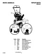
ENGLISH
ASSEMBLY
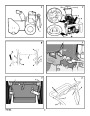
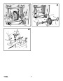
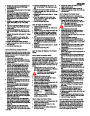
6. (Figure 4) Attach the crank rod (15) to the
universal joint assembly (16) with the hair
pin (12).
7. (Figure 3) Tighten nut on eye bolt (11).
Make sure eye bolt (11) is properly aligned
and the crank (8) can freely rotate.
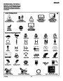
yourself with the location of various controls and
adjustments.
Read and follow the assembly and adjustment
instructions for your snow thrower. All fasteners
are in the parts bag. Do not discard any parts or
material until the unit is assembled.
Traction Drive Lever (1) - Select the forward or
reverse direction of travel.
8.
Tighten all handle fasteners.
WARNING: Before doing any
assembly or maintenance to the
snow thrower, remove the wire
from the spark plug.
Crank Assembly (2) - Changes the direction of
the discharge chute.
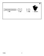
How To Install The Shift Lever Knob
(Figure 27)
1. Attach the knob (3) onto the speed shift le-
ver (2). On some models, the knob (3) is
attached. To lock in position, tighten the hex
jam nut (1) against the bottom of the knob
Discharge Chute (3) - Changes the distance the
snow is thrown.
NOTE: In this instruction book, left and right
describe the location of a part from the oper-
ator’s position behind the unit.
Auger Drive Lever (5) - Starts and stops the au-
ger and impeller (snow gathering and throwing).
NOTE: Torque is measured in foot pounds
(metric N.m). This measurement describes
how tight a nut or bolt must be. The torque is
measured with a torque wrench.
(3).
2.
Make sure the speed shift lever (2) func-
tions correctly. Move the speed shift lever
Speed Shift Lever (6) - Selects the speed of the
snow thrower.
(2)
through all speeds.
NOTE: Illustrations begin on page 3.
NOTE: Fasteners and loose parts are shown
at full size in Figure 28.
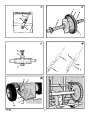
Check The Cables
Height Adjust Skid (7) - Adjusts the ground
clearance of the auger housing.
1.
(Figure 5) Check the traction drive cable
(1) and the auger drive cable (2). If the bot-
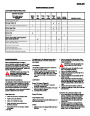
Tools Required
tom of the cables have become discon-
nected, reinstall the cables.
2. (Figure 6) If the top of the cables (5) have
become disconnected from the drive levers
Ignition Key (8) - Must be inserted to start the en-
gine.
1
1
2
2
2
1
1
Knife
Pliers
1/2 inch open end wrenches
9/16 inch open end wrenches
3/4 inch open end wrenches
Measuring tape or ruler
Screwdriver
Primer Button (9) - Injects fuel directly into the
carburetor for fast starts in cold weather.
(6), attach the cables (5) to the “Z” fitting
(7).
Electric Start Button (10) - On electric start mod-
els, used to start the engine.
How To Set The Skid Height (Figure 2)
The snow thrower is equipped with height ad-
justable skids (7) mounted on the outside of the
auger housing (4). To adjust the height of the
skids, see “How To Adjust The Height Of The
Skids” in the Maintenance section.
Switch Box (11) - On electric start models, used
to attach a 120 volt electric power cord.
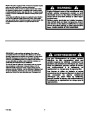
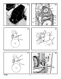
How To Remove The Snow Thrower
From The Carton
1.
2.
3.
4.
5.
6.
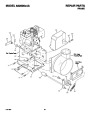
(Figure 1) The snow thrower is shown in the
shipping position.
Cut and discard the plastic tie that secures
the crank assembly.
Cut down all four corners of the carton and
lay the side panels flat.
Locate all parts that are packed separately
and remove from the carton.
Remove and discard the packing material
from around the snow thrower.
Hold onto the lower handle and pull the snow
thrower off the pallet.
Recoil Starter Handle (12) - Use to manually
start the engine.
How To Prepare The Engine
Note: The engine was shipped from the fac-
tory filled with oil. Check the level of the oil.
Add oil as needed. Engine does not contain
GASOLINE.
Throttle Control (13) - Controls the speed of the
engine.
Choke Control (14) - Use to start a cold engine.
WARNING: Follow the engine
manufacturer’s instructions for the
type of fuel and oil to use. Always
use a safety fuel container. Do not smoke
when adding gasoline to the engine. When
inside an enclosure, do not fill with gaso-
line. Before you add fuel, stop the engine.
Let the engine cool for several minutes.
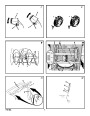
How To Control
The Discharge Of The Snow
CAUTION: DO NOT back over cables.
WARNING: Never direct the dis-
charge of snow toward bystanders.
7.
8.
Remove the packing material from the han-
dle assembly.
Cut the ties that secure the clutch control
cables (1) to the lower handle (2). Move the
cables away from the motor frame.
Check the oil. See the engine manufacturer’s
instructions for the type of fuel and oil to use.
Before you use the unit, read the information on
safety, operation, maintenance, and storage.
WARNING: Always stop the engine
before unclogging the discharge
chute or the auger housing and be-
fore leaving the snow thrower.
How To Assemble The Handle And
Crank Assembly
1.
(Figure 2) Turn the crank assembly (2) to
Important! Before You Start Operating
1.
(Figure 3) Loosen, but do not remove, the
fasteners (1) in the upper holes of the lower
handle.
change the discharge direction of the snow.
2. (Figure 7) Loosen the wing knob (1) on the
chute deflector (2).
r
Check the fasteners. Make sure all fas-
teners are tight.
2.
Remove the fasteners and the crank assem-
bly eyebolt (11) from the lower holes of the
lower handle.
3.
Move the chute deflector (2) up for more
r
On electric start models, the unit was
shipped with the starter cord plugged
into the engine. Before operating, un-
plug the starter cord from the engine.
distance or down for less distance.
4. Tighten the wing knob (1).
3.
4.
(Figure 2) Put the shift lever (6) into first
forward position.
(Figure 3) Raise the upper handle (2) to the
operating position.
How To Stop
The Snow Thrower (Figure 2)
OPERATION
NOTE: Make sure the cables are not
caught between the upper and lower han-
dle.
Install the fasteners and the crank assembly
eyebolt (11) that were removed in step 2.
DO NOT tighten until all fasteners are in
place.
1. To stop discharging snow, release the auger
drive lever (5).
2. To stop the wheels, release the traction
drive lever (1).
3. To stop the engine, push the throttle control
lever (13) to off and remove the ignition key
(8).
NOTE: Illustrations begin on page 3.
Know Your Snow Thrower (Figure 2)
5.
Read this Instruction Book and safety rules be-
fore operation the snow thrower. Compare the
illustration with your snow thrower to familiarize
12
F-031080L
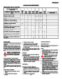
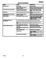
| Categories | Murray Snow Blower Manuals, Snow Blower Manuals |
|---|---|
| Tags | Murray 622505X4A |
| Download File |
|
| Document File Type | |
| Copyright | Attribution Non-commercial |
(1 votes, average: 3 out of 3)
Lawn and Garden readers have rated Murray 622505X4A Snow Blower Owners Manual 3.0 out of 3.0 based on 1 product reviews. Good. What is this trying to download manual. I won't type much more seems strange to do this. Anyway, need to check
5