


Adjustments
A
A
B
B
B
C
D
C
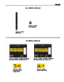
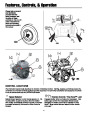
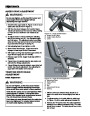
4-5/16”
(10.95cm)
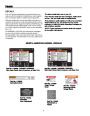
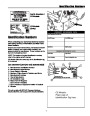
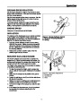
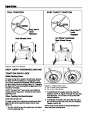
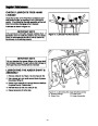
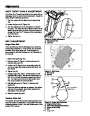
Figure 17. Traction Drive Cable Adjustment
A. Cable Boot
B. Traction Drive Cable
C. “Z” Hook
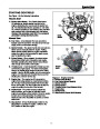
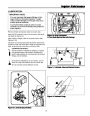
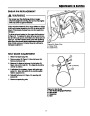
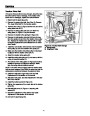
Figure 18. Friction Disc Measurement
A. Friction Disc
B. Frame
D. Cable Adjustment Bracket
A
Note: If the cable is too slack the unit will not drive. If the
cable is too tight the drive will be engaged without push-
ing the handles down.
E
B
4.
Slide the cable boot (A) over the cable adjustment
bracket.
C
Run-In Adjustment
D
ALL MODELS
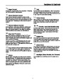
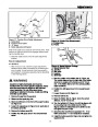
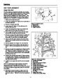
Figure 19. Speed Selector Linkage
A. Speed Selector Rod
B. Jam Nut
C. Ball Joint
D. Locknut
1.
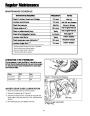
After 5 hours of use, check for proper adjustment.
Readjust clutch cable if necessary by increasing ten-
sion on cable. A small amount of arm movement is
permissible if unit passes operating checks described
in the Warning above.
E. Shift Rod
5.
Note the position of the friction disc (A, Figure 18).
The correct distance from the right side of the friction
wheel to the outside of the frame is 4-5/16” (10.95
cm). If the friction disc is not in the correct position,
adjust as follows.
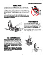
WARNING
Gasoline is highly flammable and must be
handled with care. Drain gasoline outdoors. Never
drain the tank when the engine is still hot from
recent operation. Do not allow open flame,
smoking or matches in the area. Avoid over-filling
and wipe up any spills.
6.
Position the shift speed lever in the lowest forward
speed.
7.
8.
9.
Loosen the jam nut (B, Figure 19).
Remove locknut (D).
1.
Remove the gas from the gas tank.
Disconnect the spark plug wire.
Move the friction disc (A, Figure 18) to the correct
distance, 4-5/16” (10.95 cm).
2.
3.
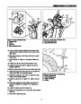
Stand snowthrower on the front of the auger housing
(C, Figure 25)
10.
Turn the ball joint (C, Figure 15) until it is aligned with
the mounting hole in the shifter rod (E). When
aligned, attach the ball joint(C) to the shifter rod (E)
and tighten the jam nut (B).
2.
Loosen the capscrews (A, Figure 25) on each side of
the bottom panel (B).
3.
4.
Remove the bottom panel (B).
11.
12.
Check that the snowthrower operates in R1. If not
follow procedures 1-11 and readjust as necessary.
Position the shift speed lever in the lowest forward
speed.
Install the bottom panel (B, Figure 25) and tighten the
capscrews (A).
25
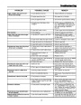
| Categories | Simplicity Snow Blower Manuals, Snapper Snow Blower Manuals, Snow Blower Manuals |
|---|---|
| Tags | Simplicity 1695302, Simplicity 1695311, Simplicity 1695313, Simplicity 1695314, Simplicity 1695410, Simplicity 1695411, Snapper 1695302, Snapper 1695311, Snapper 1695313, Snapper 1695314, Snapper 1695410, Snapper 1695411 |
| Download File |
|
| Document Type | Owner's Manual |
| Language | English |
| Product Brand | Simplicity, Snow Blower |
| Document File Type | |
| Publisher | simplicitymfg.com |
| Wikipedia's Page | Simplicity Outdoor |
| Copyright | Attribution Non-commercial |
(0 votes, average: 0 out of 5)