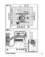
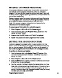

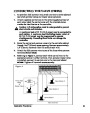
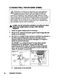


MOUNTING THE CONTROLLER
1.
Place the mounting template (provided) on the wall, positioning
the controller display area at or slightly below eye level. Using a
small punch or nail, mark the locations of the top and bottom
centerline mounting holes and the additional lower holes if extra
cabinet support is desired. (Only two mounting screws are
provided.)
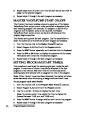
2.
3.
Drill pilot holes at least 1-1/4" (32mm) deep into the wall using a
3/32"
(2.5mm) drill for wall stud, or 1/4" (6.5mm) drill for
masonry.
For the masonry wall installation only, insert the plastic screw
anchors (provided) into the pilot holes.
Optional: The door and control module can be easily removed
from the cabinet to simplify installation. To do this, unplug the
ribbon cable connector from the control module and the two
push-on wire connectors from the bypass switch. Lift the cover
and control module up and off the hinge pins.
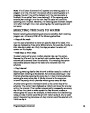
4.
5.
Place a small plastic washer and a rubber washer on each screw.
Install the #10 screws into the top and bottom locations leaving
the screw head about 1/2" (13mm) from the wall.
Note: If installing additional lower mounting screws, remove
plastic hole plugs at this time.
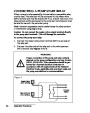
Hang the cabinet on the screws using the keyhole slots. Ensure the
screws engage the slotted portion of the keyhole with the plastic
washer positioned between the screw head and the inner cabinet
wall. Tighten the screws securely. Install additional screws in the
lower left and/or right mounting holes as required.
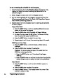
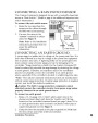
INSTALLING ELECTRICAL CONDUIT
Note: Electrical conduit and adapters are not supplied with the
controller but may be required for installation in your area. Check
local electrical codes and install conduit according to requirements.
1.
For power wires, install a 1/2" NPT threaded conduit access body to
the transformer assembly threaded nipple. From the access body,
install conduit to the source point of connection. (Domestic and
international models only.)
2.
For field (low voltage) wiring, install a 2" (52mm) conduit adapter
and conduit.
20
Installation Procedures
| Categories | Lawn Mower Manual, Sprinkler and Irrigation Manuals, Toro Sprinkler and Irrigation Manuals |
|---|---|
| Download File |
|
| Document Type | Owner's Manual |
| Language | English |
| Product Brand | Toro. Customer Service Representatives are available by phone:
Monday - Friday 7:30 a.m. to 9:00 p.m. (CDT) - Saturday 8:00 a.m. to 8:00 p.m. (CDT) - Sunday 10:00 a.m. to 8:00 p.m. (CDT)
Canada 1-888-225-4886 USA 1-888-384-9939, Lawn Mower |
| Document File Type | |
| Publisher | toro.com |
| Wikipedia's Page | Toro Company |
| Copyright | Attribution Non-commercial |
(0 votes, average: 0 out of 5)