

SECTION 8: ADJUSTMENTS
WARNING: NEVER attempt to clean
chute or make any adjustments while
engine is running.
3. If adjustment is necessary, loosen the lock nut
on the traction drive cable and thread the cable
in or out as necessary. Tighten the lock nut to
secure the cable when correct adjustment is
reached. Reassemble the frame cover.
CHUTE ASSEMBLY ADJUSTMENT
The distance snow is thrown can be controlled by
adjusting the angle of the top section of the chute
assembly.
NOTE: If you placed plastic under the gas cap, be
certain to remove it.
AUGER CLUTCH ADJUSTMENT
SKID SHOE ADJUSTMENT
To adjust the auger clutch, refer to Final Assembly
and Adjustments section on page 10.
The space between the shave plate and the ground
can be adjusted. Refer to the Final Assembly and
Adjustments section.
CARBURETOR ADJUSTMENT
WARNING: If any adjustments are
made to the engine while the engine is
running (e.g. carburetor), keep clear of
all moving parts. Be careful of heated
surfaces and muffler.
TRACTION DRIVE CLUTCH
ADJUSTMENT
Refer to the Final Assembly and Adjustments
section to adjust the traction drive clutch. If you are
uncertain that you have reached the correct
adjustment,
checked as follows.
the adjustment can be physically
Minor carburetor adjustment may be required to
compensate for differences in fuel, temperature,
altitude and load.
Refer to the separate engine manual packed with
your unit for carburetor adjustment information.
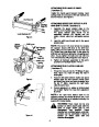
1.
With the snow thrower tipped forward (be
certain to drain the oil gasoline or drain the oil
and place plastic film under the gas cap if the
snow thrower has already been operated),
remove the frame cover underneath the snow
thrower by removing six self-tapping screws.
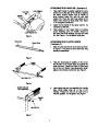
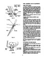
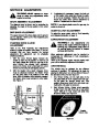
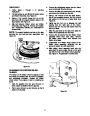
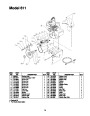
DRIVE WHEELS
The wheels may be adjusted for two different
methods of operation. The adjustment is made by
placing the klick pins in one of two different holes on
the right side of the unit. See Figure 22.
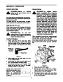
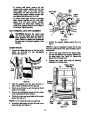
2.
With the traction drive clutch released, there
must be clearance between the friction wheel
and the drive plate in all positions of the shift
lever. With the traction drive clutched engaged,
the friction wheel must contact the drive plate.
See Figure 21.
1.
2.
One Wheel Driving—On the right side of the
unit, place klick pin in the outside axle hole only.
Do not place pin through wheel hub. This
position gives power drive to the left wheel only,
making the unit easier to maneuver.
Both Wheels Driving—Rotate wheel assembly
to align hole in hub with inner hole on axle shaft.
Friction
Wheel
Insert
klick pin in hole. Outer axle shaft hole
should be visible. See Figure 22.
Klick Pin in Hub
Holeand Inner AxleHole
Gear Shaft
Drive
Plate
Outside
Hole in Axle
Figure 22
Figure 21
14
| Categories | MTD Snow Blower Manuals, Snow Blower Manuals, Yard Machines Snow Blower Manuals |
|---|---|
| Tags | MTD 611, MTD Snow Blower Manual, Yard Machines 611 |
| Download File |
|
| Document Type | Owner's Manual |
| Language | English |
| Product Brand | Yard Machines, 611, Snow Blower |
| Document File Type | |
| Publisher | mtdproducts.com |
| Wikipedia's Page | MTD Products |
| Copyright | Attribution Non-commercial |
(0 votes, average: 0 out of 5)