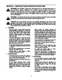
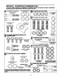
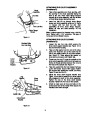
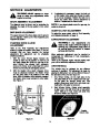
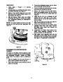


ATTACHING THE HANDLE PANEL
(Hardware C)
Position the handle panel between handles. Insert
carriage bolts (E) and secure with lock washers (C)
and hex nuts (D). See Figure 8.
Hex Nuts (D)
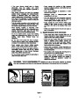
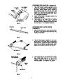
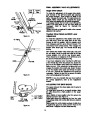
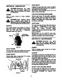
ATTACHING SPEED SELECTOR PLATE
AND SHIFT LEVER (Hardware D)
Carriage
Bolts (E)
1.
Assemble the speed selector plate to the
outside of the handles as shown in Figure 9.
The
assembled
speed
selector
between
plate
should
not
and
be
the
Lock Washers (C)
the
handles
engine. Secure using four self-tapping screws
(F).
Figure 8
2.
Insert the shift lever through slot in the speed
selector plate.
Speed
Selector
Plate
Shift Lever
NOTE: The bend in the lever should be towards
the operator. Secure shift lever to the shift lever
spring using two hex bolts (G) and hex lock nuts
(H). Tighten both bolts finger tight. At this point the
shift lever and shift lever spring are not against each
other. As you tighten the bolts and nuts with two
Self-Tapping
Screw (F)
Hex
Bolts (G)
7/16"
wrenches they will pull together. See Figure 9.
3.
Tighten all hardware assembled to this point.
CLUTCH GRIPS MUST MOVE FREELY.
Shift Lever
Spring
Hex Lock
Nuts (H)
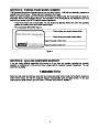
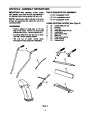
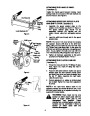
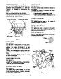
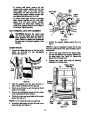
ATTACHING THE CLUTCH CABLES
(Hardware E)
1.
Thread hex nuts (J) onto the “Z” fittings (R) (see
inset, Figure 10). Insert “Z” fitting into hole in
clutch grips.
2.
Route the left cable between engine and speed
selector plate and then between handle panel
and clutch lever pivot rod before threading onto
the left “Z” fitting. Assemble the right cable
using the same route.
Figure 9
3.
Correct adjustment on cables is minimal slack
but not tight. Tighten hex nuts when adjustment
is correct.
“Z” Fitting
(R)
NOTE: If the right hand lockout cable is not
adjusted correctly, the wheels will tend to turn. If the
left hand lockout cable is not adjusted correctly, the
augers will not stop rotating.
Hex
Nut
(J)
WARNING: There must not be any
tension on either clutch cable with the
drive
or auger clutch grip in the
disengaged
(up)
position.
These
clutches are a safety feature, and their
function can be overridden if there is
Figure 10
tension
on
either
cable
with
the
clutches disengaged.
8
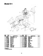
| Categories | MTD Snow Blower Manuals, Snow Blower Manuals, Yard Machines Snow Blower Manuals |
|---|---|
| Tags | MTD 611, MTD Snow Blower Manual, Yard Machines 611 |
| Download File |
|
| Document Type | Owner's Manual |
| Language | English |
| Product Brand | Yard Machines, 611, Snow Blower |
| Document File Type | |
| Publisher | mtdproducts.com |
| Wikipedia's Page | MTD Products |
| Copyright | Attribution Non-commercial |
(0 votes, average: 0 out of 5)