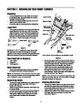
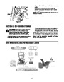


Friction Wheel Rubber
Drive Belts
Follow the instructions below to check the condition of
the friction wheel rubber every 25 hours of operation.
Follow the instructions below to check the condition of
the drive belts every 50 hours of operation.
•
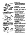
Remove the six self-tapping screws from the frame
cover underneath the snow thrower.
Visually inspect the friction wheel rubber for
excessive wear, cracks, or loose fit on the friction
wheel drive hub.
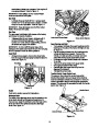
Also engage the traction control and check if the
friction wheel is making contact with friction plate.
Refer to Figure 11. If it does not make contact,
adjust the traction drive cable and recheck the
friction wheel.
•
•
•
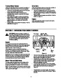
Remove the plastic belt cover on the front of the
engine by removing the three self-tapping screws.
Visually inspect for frayed, cracked, or excessively
worn out belts.
Replace belts as necessary as outlined in Service
Section on page 15.
•
•
•
Engine
Follow accompanying engine manual for all engine-
related maintenance issues.
Replace friction wheel rubber if necessary. Refer to
instructions on page 16.
SECTION 7: SERVICING YOUR SNOW THROWER
WARNING: Before servicing, repairing, or
Shear Bolts
inspecting, disengage all clutch levers and stop
engine. Wait until all moving parts have come
to a complete stop. Disconnect spark plug wire
and ground it against the engine to prevent
unintended starting.
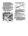
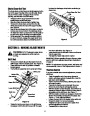
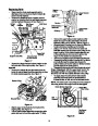
Augers
The augers are secured to the spiral shaft with two
shear bolts and hex lock nuts. If you hit a foreign object
or ice jam, the snow thrower is designed so that the
bolts may shear. Refer to Figure 13.
If the augers do not turn, check if the bolts have
sheared. Two replacement shear bolts and hex lock
nuts have been provided with the snow thrower. Refer
to Loose Parts in the Assembly Section.
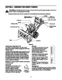
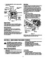
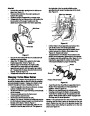
Washer
Carriage
Bolt
Shave
Plate
Hex Nut
Figure 16
IMPORTANT: NEVER replace the auger shear bolts with
standard hex bolts. Any damage to the auger gearbox
or other components, as a result of doing so, will NOT
be covered by your snow thrower’s warranty.
•
•
Remove the six carriage bolts, belleville washers
and hex nuts which attach two skid shoes to the
snow thrower on two sides. See Figure 12.
Reassemble new skid shoes with the hardware
removed earlier (cupped side of belleville washer
against the skid shoes). Make certain the skid
shoes are adjusted to be level.
To remove the shave plate, remove the carriage
bolts, belleville washers and hex nuts which attach
shave plate to the snow thrower housing.See
Figure 16.
Shave Plate and Skid Shoes
The shave plate and skid shoes on the bottom of the
snow thrower are subject to wear. These should be
checked periodically and replaced when necessary.
•
•
NOTE: The skid shoes on this machine have two wear
edges. When one side wears out, they can be rotated
180° to use the other edge.
Reassemble the new shave plate, with heads of
carriage bolts to the inside of the housing. Tighten
securely.
14
| Categories | MTD Snow Blower Manuals, Snow Blower Manuals, Yard Man Snow Blower Manuals |
|---|---|
| Tags | MTD 31AE993I401, MTD Snow Blower Manual, Yard Man 31AE993I401 |
| Download File |
|
| Document Type | Owner's Manual |
| Language | English |
| Product Brand | Yard-Man, 31AE993I401, Snow Blower |
| Document File Type | |
| Publisher | mtdproducts.com |
| Wikipedia's Page | MTD Products |
| Copyright | Attribution Non-commercial |
(0 votes, average: 0 out of 5)