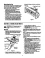
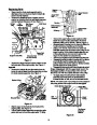
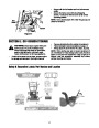


Drive Belt
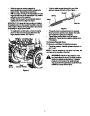
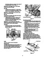
the right side of the hex shaft will fall and the
sprocket should remain hanging lose in the chain.
See Figure 22.
•
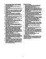
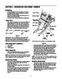
Unhook the extension spring from the belt cover
plate. See Figure 21.
•
Remove drive belt from the engine pulley and
bottom drive pulley.
Shift Arm Assembly
•
•
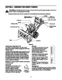
Replace belt and reassemble in reverse order.
Reassemble the two halves of the unit hooking the
lower portion of the auger housing over the
stationary shoulder bolts in the frame assembly.
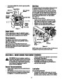
Shift Arm
Assembly
Sprocket
SpSpacerrocket
Spacer
Pin
Pin
Belt Cover
Friction
Wheel
Drive Cover
Friction Wheel
Extension
Spring
Figure 22
•
•
Lift the friction wheel assembly out between the
axle shaft and the drive shaft assemblies.
Remove four screws securing the friction wheel
rubber between the friction wheel plates. See
Figure 23. Discard old rubber.
Drive Belt
•
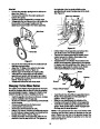
Reassemble the new friction wheel rubber to the
friction wheel assembly, tightening the four screws
in rotation and with equal force. See Figure 23. It is
important to assemble the rubber on the friction
wheel symmetrically for proper functioning.
Figure 21
•
•
Secure the two halves with the two bolts and lock
washers removed earlier.
Attach the “Z” fitting of the cable into the brake
bracket assembly. Refer to Figure 19.
•
•
Slip the auger control belt over engine pulley.
Insert ferrule on auger idler rod into bracket
assembly and secure with flat washer and cotter
pin. Reassemble the large shoulder bolt and lock
washer. Refer to Figure 19.
Plates
Bearing
Screws
Hub
•
Reassemble belt cover and chute crank.
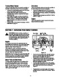
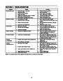
Changing Friction Wheel Rubber
The rubber on the friction wheel is subject to wear and
should be checked after the first 25 hours of operation,
and periodically thereafter. Replace the friction wheel
rubber if any signs of wear or cracking are found.
Friction Wheel Rubber
Figure 23
•
Insert the pin from the shift arm assembly into the
friction wheel assembly and hold assembly in
position. Refer to Figure 22.
Slide the hex shaft through the left side of the
housing and through the friction wheel assembly.
Insert the hex shaft through the sprocket and the
spacer. Make certain that the chain engages both
the large and the small sprocket.
•
•
•
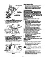
Drain the gasoline from the snow thrower, or place
a piece of plastic under the gas cap.
Tip the snow thrower up and forward, so that it rests
on the housing.
Remove six screws from the frame cover
underneath the snow thrower.
•
•
•
•
Remove the left wheel from the axle.
Using a 7/8” wrench, hold the hex shaft and remove
the hex bolts and cupped washer and bearing from
left side of the frame. Refer to Figure 11.
Holding the friction wheel assembly, slide the hex
shaft out of the left side of the unit. The spacer on
NOTE: If the sprocket fell from the snow thrower while
removing the hex shaft, place the sprocket on the hex
shaft. Position the hex hub of the sprocket toward the
friction wheel when sliding the sprocket on to the hex
shaft. See Figure 24.
•
16
| Categories | MTD Snow Blower Manuals, Snow Blower Manuals, Yard Man Snow Blower Manuals |
|---|---|
| Tags | MTD 31AE993I401, MTD Snow Blower Manual, Yard Man 31AE993I401 |
| Download File |
|
| Document Type | Owner's Manual |
| Language | English |
| Product Brand | Yard-Man, 31AE993I401, Snow Blower |
| Document File Type | |
| Publisher | mtdproducts.com |
| Wikipedia's Page | MTD Products |
| Copyright | Attribution Non-commercial |
(0 votes, average: 0 out of 5)