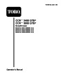
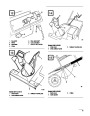


Install Discharge Chute (Fig. 5)
3.
4.
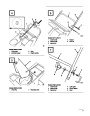
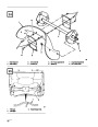
Route cable through elongated hole in cable
adjuster. Insert Z fitting on end of cable into 3rd
hole on cable adjuster (Fig. 9).
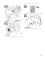
Models 38433 & 38438
Slide spring cover over spring and cable adjuster.
Push spring end through hole at end of spring
cover (Fig. 8).
1.
Set discharge chute onto chute ring. Align hole
in back of chute with center hole in ring and
install a carriage bolt and sems locknut. Position
nut on outside of chute.
5.
6.
Hook spring into top hole of control bar bracket
(Fig. 8).
Note:
Chute ring may be rotated to ease
assembly of discharge chute.
Move control bar back toward handle until slack
in cable is removed. The gap between the control
bar bracket and handle should be approximately
2.
Secure chute to remaining holes in chute ring
and tighten all nuts SECURELY.
1/16”-1/8”.
See insert, Figure 8. If an adjustment
is required, refer to Adjusting Control Bar,
page 13.
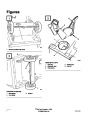
Install Handle
Note:
The control cable must always have
slack in it when in the disengaged
position.
1.
2.
3.
Remove tie securing control cable to lower
handle.
Position upper handle so that control bar is on
top of handle, not underneath it.
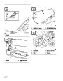
Install Control Cable
Models 38412 & 38418 – Secure upper handle
in place with (3) handle bolts, (1) eyebolt, and
(4)
side of handle. Eyebolt must be positioned
lock nuts. Use eyebolt to mount upper left
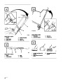
Models 38433 & 38438
perpendicular to handle when tightened (Fig. 6).
1.
2.
Route control cable through cable guide on left
side of snowthrower (Fig. 10).
Models 38433 & 38438 – Secure upper handle
in place with (2) handle locks, (1) cable guide,
Hook upper end of control cable in rear hole
(hole with arrow) in control bar bracket
(Fig. 10).
(2)
curved washers and (2) knobs. Cable guide
must be perpendicular to handle with loop facing
out and up (Fig. 7).
3.
Move control bar back toward handle until slack
in cable is removed. The gap between bottom of
handle and stop on control bar (left hand side on
bottom of handle) should be approximately
1/16”-1/8”. See insert, Figure 10. If an
adjustment is required, refer to Adjusting
Control Bar, page 13.
Install Control Cable
Models 38412 & 38418
1.
2.
Route control cable through eyebolt on left side
of snowthrower (Fig. 8).
Note:
The control cable must always have
slack in it when in the disengaged
position.
Hook spring to round hole at end of cable
adjuster (Fig. 9).
9
| Categories | Snow Blower Manuals, Toro Snow Blower |
|---|---|
| Tags | Toro 38412, Toro 38418, Toro 38433, Toro 38438, Toro CCR 2400, Toro CCR 3000 |
| Model Year | 1999 |
| Download File |
|
| Document Type | Operator's Manual |
| Language | English |
| Serial Number | 9900001 - 9999999 |
| Product Name | 38412, 38418, 38433, 38438 |
| Product Brand | Toro. Customer Service Representatives are available by phone:
Monday - Friday 7:30 a.m. to 9:00 p.m. (CDT) - Saturday 8:00 a.m. to 8:00 p.m. (CDT) - Sunday 10:00 a.m. to 8:00 p.m. (CDT)
Canada 1-888-225-4886 USA 1-888-384-9939, Snow Blower |
| Product Type | Snowthrower |
| Product Series | CCR 1000/2400/2500, Single Stage, Snowthrower |
| Swath | 20 inch |
| Discharge | Single Stage |
| Engine Manufacturer | Toro |
| Engine Oil Type | Toro 2 cycle / NMMA-TCW3 |
| Engine Motor Model # | R-tek |
| Engine Motor Size | 4 hp |
| Engine Motor Type | 2 Cycle EPA1 |
| Document File Type | |
| Publisher | toro.com |
| Wikipedia's Page | Toro Company |
| Copyright | Attribution Non-commercial |
(0 votes, average: 0 out of 5)