
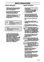

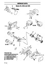
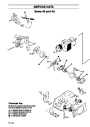
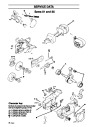
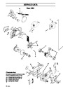
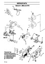


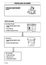

CARBURETTOR
Description
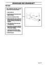
!
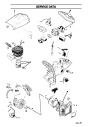
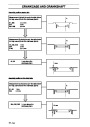
The diagrams in this description do not
correspond with the carburettor fitted on
the chain saws. They serve only to show
the principles of design and operation.
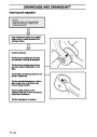
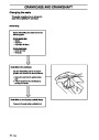
WARNING!
The fuel used in the chain saw poses
the following hazards:
1. The liquid and its vapours are
poisonous.
2.
3.
Can cause skin irritation.
Is highly inflammable.
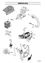
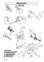
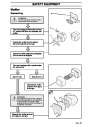
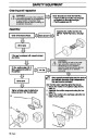
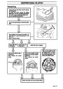
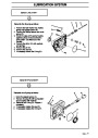
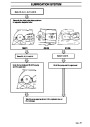
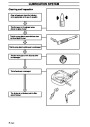
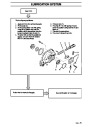
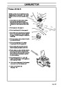
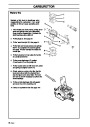
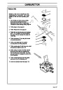
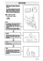
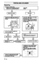
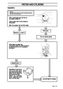
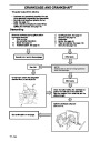
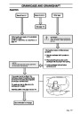
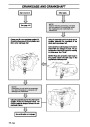
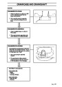
Design
The carburettor consists of three sub-systems:
•
•
•
Metering unit, A.
Mixing venturi, B.
Pump unit, C.
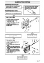
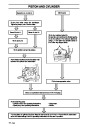
The metering unit (A) contains the jets and
fuel control functions. It is here the correct
amount of fuel for the given engine speed
and power is metered.
A
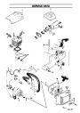
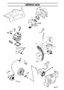
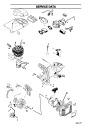
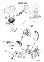
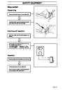
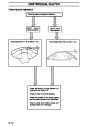
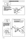
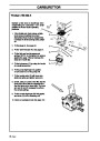
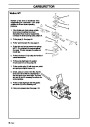
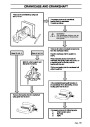
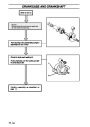
The mixing venturi (B) houses the choke,
throttle valve and diffuser jets. Here air is
mixed with the fuel to give a fuel/air
mixture that can be ignited by the ignition
spark.
B
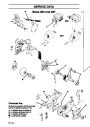
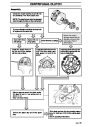
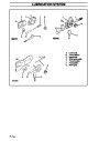
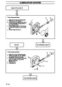
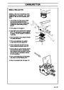
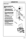
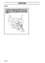
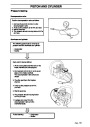
In the pump unit (C), fuel is pumped from the
fuel tank to the metering unit. One side of the
pump diaphragm is connected to the crankcase
and pulses in time with the pressure changes in
the crankcase. The other side of the diaphragm
pumps the fuel.
C
English –
83
| Categories | Chainsaw Manuals, Husqvarna Chainsaw Manuals |
|---|---|
| Tags | Husqvarna 242XP, Husqvarna 246, Husqvarna 254XP, Husqvarna 257, Husqvarna 262XP, Husqvarna 268, Husqvarna 268K, Husqvarna 272K, Husqvarna 272S, Husqvarna 272XP, Husqvarna 281XP, Husqvarna 288XP, Husqvarna 3120XP, Husqvarna 36, Husqvarna 394XP, Husqvarna 40, Husqvarna 41, Husqvarna 42, Husqvarna 45, Husqvarna 51, Husqvarna 55, Husqvarna 61 |
| Model Year | 1997, 1998, 1999, 2000, 2001, 2002 |
| Download File |
|
| Document Type | Operator's Manual |
| Language | English |
| Product Brand | Husqvarna, Chainsaw |
| Document File Type | |
| Publisher | husqvarna.com |
| Wikipedia's Page | Husqvarna |
| Copyright | Attribution Non-commercial |
(0 votes, average: 0 out of 5)