


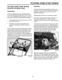
ELECTRIC START SYSTEM (12 VOLT)
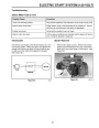
Alternator Output Testing
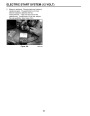
Alternator Resistance Check
1.
To check output of the alternator accurately, it is
necessary to run the engine at operating speed,
± 300 RPM. Readjust the governor if
necessary. Refer to page 26 (Presetting the
Governor (DuraForce Engines Only).
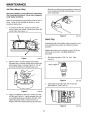
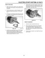
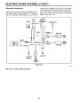
1. Disconnect the electronic cup assembly from the
wiring harness. Connect one ohmmeter (RX-1
scale) lead to the green wire of the wiring harness
and the other to the engine block. (See Figure
105.)
2900
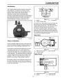
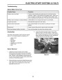
2.
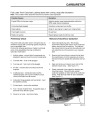
With the engine running, unplug the battery
connector and reconnect the plug so that only the
black wires are connected. Using a multimeter, set
to read 500 milliamps. Connect the red lead to the
red wire going to the battery and the black lead to
the red wire going to the mower.
2. Measure resistance. The resistance should be
from 2.7 to 3.3 ohms. If specification is not met,
check resistance at alternator connection. If
specification is met at the alternator, look at the
harness for breakage. If specification is not met at
alternator connection, replace the alternator.
CAUTION: Keep hands and feet away from the
blade.
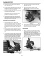
3.
Measure alternator output. The reading should be
from 190-450 M.A. (Milliampere) at 2900 ± 300
RPM. If output is not within specification, check
the alternator air gap.
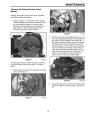
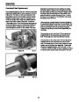
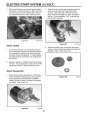
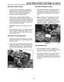
Alternator Air Gap Adjustment
1.
Rotate the flywheel until the magnets are directly
adjacent to the alternator. There should be a .010”
(.25
mm) air gap.
Figure 105
0891-004
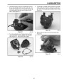
2.
If gap is incorrect, loosen the alternator mounting
bolts slightly allowing the flywheel magnets to pull
alternator against the gauge. Tighten the bolts to
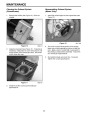
Cup Assembly Test
75
104.)
in. lbs., and recheck the air gap. (See Figure
1.
The cup assembly consists of a capacitor and
diode. Its function is to convert alternating current
to direct current and increase the voltage.
2.
Disconnect the electronic cup assembly from the
wiring harness. Connect one ohmmeter (RX-1
scale) lead to the green wire of the cup side of the
connector and the other lead to the red wire of the
connector.
Figure 104
6.tif
57
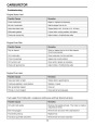
| Categories | Snow Blower Manuals, Toro Snow Blower |
|---|---|
| Model Year | 2005 |
| Download File |
|
| Language | English |
| Product Brand | Toro. Customer Service Representatives are available by phone:
Monday - Friday 7:30 a.m. to 9:00 p.m. (CDT) - Saturday 8:00 a.m. to 8:00 p.m. (CDT) - Sunday 10:00 a.m. to 8:00 p.m. (CDT)
Canada 1-888-225-4886 USA 1-888-384-9939, Snow Blower |
| Document File Type | |
| Publisher | toro.com |
| Wikipedia's Page | Toro Company |
| Copyright | Attribution Non-commercial |
(0 votes, average: 0 out of 5)