


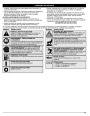


OPERATING INSTRUCTIONS
TIPS FOR BEST TRIMMING RESULTS
• Adherence of the listed trimming techniques
•
•
Keep the cutting attachment parallel to the ground.
• What vegetation is cut
• Where vegetation is cut
For example, the line will wear faster when trimming against a
foundation wall as opposed to trimming around a tree.
Do not force the cutting attachment. Allow the tip of the line to do
the cutting, especially along walls. Cutting with more than the tip
will reduce cutting efficiency and may overload the engine.
Cut grass over 8 inches (200 mm) by working from top to bottom
in small increments to avoid premature line wear or engine drag.
Cut from right to left whenever possible. Cutting to the left
improves the unit's cutting efficiency. Clippings are thrown away
from the operator.
Slowly move the trimmer into and out of the cutting area at the
desired height. Move either in a forward-backward or side-to-side
motion. Cutting shorter lengths produces the best results.
•
•
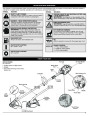
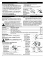
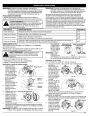
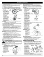
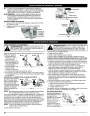
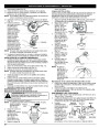
DECORATIVE TRIMMING
Decorative trimming is
BL150
BL100
accomplished by
removing all vegetation
around trees, posts,
fences, etc.
•
Rotate the whole unit so
that the cutting attachment
is at a 30° angle to the
ground (Fig. 11).
•
•
Trim only when grass and weeds are dry.
The life of your cutting line is dependent upon;
Fig. 11
MAINTENANCE AND REPAIR INSTRUCTIONS
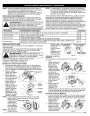
MAINTENANCE SCHEDULE
NOTE: Maintenance, replacement, or repair of the emission control
devices and system may be performed by any non-road
engine repair establishment, individual or authorized service
dealer.
Perform these required maintenance procedures at the frequency
stated in the table. These procedures should also be a part of any
seasonal tune-up.
In order to assure peak performance of your engine, inspection of the
engine exhaust port may be necessary after 50 hours of operation. If
you notice lost RPM, poor performance or general lack of acceleration,
this service may be required. If you feel your engine is in need of this
inspection, refer service to any non-road engine repair establishment,
individual or authorized service dealer for repair. DO NOT attempt to
perform this process yourself as engine damage may result from
contaminants involved in the cleaning process for the port.
NOTE: Some maintenance procedures may require special tools
or skills. If you are unsure about these procedures take
your unit to any non-road engine repair establishment,
individual or authorized service dealer.
WARNING:
To prevent serious injury, never perform
maintenance or repairs with unit running. Always service
and repair a cool unit. Disconnect the spark plug wire to
ensure that the unit cannot start.
FREQUENCY
MAINTENANCE REQUIRED
SEE
Before starting engine
Every 10 hours
Fill fuel tank with fresh fuel
p. 4
Clean and re-oil air filter
p. 7
Check and clean spark arrestor
Check spark plug condition and gap
p. 8
p. 8
Every 25 hours
Inspect exhaust port and spark arrestor screen for clogging or obstruction to assure maximum
performance levels.
Every 50 hours
p. 8
inner surface of the
outer spool.
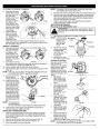
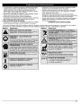
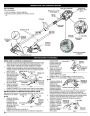
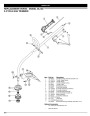
LINE INSTALLATION
This section covers both SplitLine™ and standard single line
installation.
Always use original equipment manufacturer 0.080 in. (2.03 mm)
replacement line. Line other than the specified may make the
engine overheat or fail.
Outer Spool
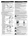
5.
Check the indexing
teeth on the inner
reel and outer spool
for wear (Fig. 14). If
necessary, remove
burrs or replace the
reel and spool.
NOTE: SplitLine™ can
only be used with
the inner reel with
the slotted holes.
Single line can be
used on either
type of inner reel.
Use Figure 15 to
identify the inner
reel you have.
NOTE: Always use the
correct line
Spring
Inner Reel
WARNING:
or rope. These can break off and become dangerous
projectiles.
Never use metal-reinforced line, wire, chain
Fig. 13
Indexing Teeth
There are two methods to replace the trimming line:
•
•
Wind the inner reel with new line
Install a prewound inner reel
Winding the Existing Inner Reel
1.
Hold the outer spool
with one hand and
unscrew the Bump
Knob™
Bolt
Bump Knob™
Fig. 14
For Use with
Single Line ONLY
For Use with Splitline™
or Single Line ONLY
counterclockwise
(Fig. 12). Inspect the
bolt inside the
Bump Knob to
make sure it moves
length when
installing
trimming line on
the unit. The line
may not release
properly if the
line is too long.
Fig. 12
Slotted
Holes
freely. Replace the Bump Knob if damaged.
Fig. 15
2.
3.
4.
Remove the inner reel from the outer spool (Fig. 13).
Remove spring from the inner reel (Fig. 13).
Use a clean cloth to clean the the inner reel, spring, shaft, and
Single Line Installation
6
| Categories | Bolens Trimmer Manuals, Lawn Mower Manual, MTD Lawn Mower Manuals, MTD Trimmer Manuals, Trimmer Manuals |
|---|---|
| Tags | Bolens BL100, Bolens BL150, MTD BL100 MTD BL150 |
| Download File |
|
| Document Type | Owner's Manual |
| Language | English |
| Product Brand | MTD, Lawn Mower |
| Product Type | Walk Behind Mower |
| Document File Type | |
| Publisher | mtdproducts.com |
| Wikipedia's Page | MTD Products |
| Copyright | Attribution Non-commercial |
(0 votes, average: 0 out of 5)