


ENGLISH
5.
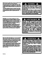
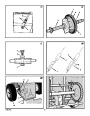
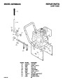
(Figure 14) Loosen the belt guide (9). Pull
the belt guide (9) away from the auger
drive pulley (10).
Pull the idler pulley (3) away from the auger
drive belt (4).
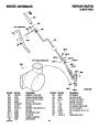
Remove the old auger drive belt (4) from
the auger drive pulley (10) and from the en-
gine pulley (11). Replace the auger drive
belt (4) with an original factory replacement
belt available from an authorized service
center.
12.Adjust the belt guide (9). See “How To Ad-
just The Belt Guide” in the Maintenance sec-
tion.
13.(Figure 16) Install the bottom panel (2).
14.Tighten the bolts (3) on each side of the bot-
tom panel (2).
4. (Figure 19) Tighten the bolts (1) on the
speed control rod (8).
5. (Figure 16) Install the bottom panel (2).
6. Tighten the bolts (3) on each side of the bot-
tom panel (2).
6.
7.
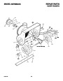
How To Replace The Friction Wheel
15.(Figure 13) Install the belt cover (1). Tighten
screw (2).
If the friction wheel is worn or damaged, the
snow thrower will not move forward. The friction
wheel must be replaced as follows.
16.
Check the adjustment of the cables. See
“How To Check And Adjust The Cables” in
the Maintenance section.
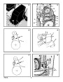
1.
(Figure 2) Remove the gas from the gas
tank. Stand the snow thrower up on the front
end of the auger housing (4).
8.
Install the new auger drive belt (4) onto the
auger drive pulley (10) and onto pulley
17.Connect the spark plug wire.
(11).
How To Adjust The Belt Guide
WARNING: Drain the gasoline out-
doors, away from fire or flame.
9.
Adjust the auger drive belt (4). See “How To
Adjust The Auger Drive Belt” in the Mainte-
nance section.
Adjust the belt guide (9). See “How To Ad-
just The Belt Guide” in the Maintenance sec-
tion.
(Figure 13) Install the belt cover (1). Tighten
screw (2).
Check the adjustment of the cables. See
“How To Check And Adjust The Cables” in
the Maintenance section.
1.
2.
Disconnect spark plug wire.
(Figure 13) Remove screw (2). Remove the
belt cover (1).
2.
3.
Disconnect the spark plug wire.
10.
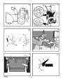
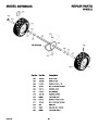
(Figure 23) Remove the fasteners that se-
cure the left wheel (10). Remove the left
wheel (10) from the axle (11).
3.
4.
(Figure 2) Engage the auger drive lever (5).
(Figure 17) Measure the distance between
the belt guide (2) and auger drive belt (3).
The correct distance (4) is 1/8 inch (3.175
mm).
11.
12.
4.
Loosen the bolts (3) on each side of the bot-
tom panel (2).
5.
6.
Remove the bottom panel (2).
(Figure 24) Remove the fasteners that se-
cure the drive sprocket (12) to the axle (11).
5.
If an adjustment is necessary, loosen the
mounting bolt for the belt guide (2). Move
the belt guide (2) to the correct position
13.
14.
(Figure 16) Install the bottom panel (2).
Tighten the bolts (3) on each side of the bot-
tom panel (2).
(4). Tighten the mounting bolt for the belt
7. Remove the right wheel, axle (11), and drive
sprocket (12).
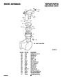
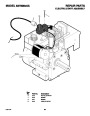
8. (Figure 25) Remove the four bolts (16) that
hold the bearings (7) on each side of the
hex shaft (8).
guide (2).
6.
7.
(Figure 13) Install the belt cover (1). Tighten
screw (2).
Connect the spark plug wire.
15.
Connect the spark plug wire.
9.
(Figure 26) Remove the hex shaft (8) and
bearings (7).
How To Remove the Traction Drive Belt
How To Adjust Or Replace The Friction
Wheel
NOTE: Take special note of the position of
the washers (17) .
If the snow thrower will not move forward, check
the traction drive belt for wear or damage. If the
traction drive belt is worn or damaged, replace
the belt as follows.
10.
11.
12.
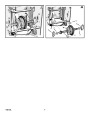
(Figure 20) Remove the three fasteners (4)
that hold the friction wheel (5) to the hub
(6).
(Figure 20) Remove the friction wheel (5)
from the hub (6). Slip the friction wheel (5)
off the hex shaft (8).
How To Check The Friction Wheel
If the snow thrower will not move forward, check
the traction drive belt, the traction drive cable or
the friction wheel. If the friction wheel is worn or
damaged, it must be replaced. See “How To
Replace the Friction Wheel” in this section. If the
friction wheel is not worn or damaged, check as
follows.
1.
2.
Disconnect the spark plug wire.
Remove the auger drive belt. See “How To
Remove The Auger Drive Belt” in the Mainte-
nance section.
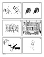
(Figure 14) Remove the e-ring (17) from
one end of the swing plate axle rod (18).
Remove the swing plate axle rod (18) to
allow the the swing plate to pivot forward.
Assemble the new friction wheel (5) onto
hub (6) with the fasteners removed earlier.
3.
13.(Figure 26) Install the hex shaft (8) and
bearings (7) with the four bolts removed ear-
lier.
Make sure the washers (17) are properly
installed in the original position. Also,
make sure the two washers (13) are prop-
erly aligned with the actuator arms (14).
1.
(Figure 2) Remove the gas from the gas
tank. Stand the snow thrower up on the front
end of the auger housing (4).
4.
5.
Remove the traction drive spring (16).
Remove the old traction drive belt (13) from
the traction drive pulley (14) and from the
engine pulley (15). Replace the traction
drive belt (13) with an original factory re-
placement belt available from an authorized
service center.
Install the new traction drive belt (13) onto
the traction drive pulley (14) and onto en-
gine pulley (15).
WARNING: Drain the gasoline out-
doors, away from fire or flame.
14.
15.
Make sure the hex shaft (8) turns freely.
(Figure 24) Install the right wheel, axle (11),
and drive sprocket (12) with the fasteners
removed earlier. Install the chain (15) onto
the drive sprocket (12).
2.
3.
Disconnect the spark plug wire.
(Figure 16) Loosen the bolts (3) on each
side of the bottom panel (2).
6.
7.
4.
Remove the bottom panel (2).
5. (Figure 2) Position the shift speed lever (6)
in the lowest forward speed.
16.
Check the adjustment of the friction wheel.
See “How To Adjust The Friction Wheel” in
this section.
Make sure the traction drive idler pulley
6.
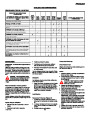
(Figure 18) Note the position of the friction
wheel (4). The correct distance “A” from the
right side of the friction wheel (4) to the out-
side of the motorbox is as follows:
(12)
is properly aligned with the traction
drive belt (13).
Attach the traction drive spring (16).
Install the swing plate axle rod (18) and se-
cure with the e-ring (17) removed earlier.
(Figure 25) The bottom of the swing plate
17.Make sure the friction wheel and the disc
drive plate are free from grease or oil.
18.(Figure 16) Install the bottom panel (2).
19.Tighten the bolts (3) on each side of the bot-
tom panel (2).
20.(Figure 23) Install the left wheel (10) to the
axle (11) with the fasteners removed earlier.
21.Connect the spark plug wire.
8.
9.
Tire Size
Distance “A”
12
16
and 13 inch
inch
4-1/8” (10.5 cm.)
4-5/16” (10.95 cm.)
10.
(20)
must be positioned between the align-
ment tabs (19). Make sure the swing plate
is properly secured.
If the friction wheel (4) is not in the correct
position, adjust as follows.
(20)
NOTE: If the drive will not engage after
the traction drive belt has been replaced,
then check to make sure that the swing
plate is positioned between the alignment
tabs (19).
How To Adjust The Friction Wheel
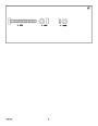
How To Replace the Auger Shear Bolt
1. (Figure 2) Position the shift speed lever (6)
in the lowest forward speed.
2. (Figure 19) Loosen the bolts (1) on the
speed control rod (8).
3. (Figure 18) Move the friction wheel (4) to
The augers are secured to the auger shaft with
special shear bolts. These shear bolts are de-
signed to break and protect the machine if an
object becomes lodged in the auger housing.
Do not use a harder bolt as the protection pro-
vided by the shear bolt will be lost.
11.
(Figure 14) Install and adjust the auger
drive belt (4). See “How To Remove The
Auger Drive Belt” in the Maintenance section.
the correct position.
17
F-031012L
| Categories | Murray Snow Blower Manuals, Snow Blower Manuals |
|---|---|
| Tags | Murray 627808X5A |
| Download File |
|
| Document File Type | |
| Copyright | Attribution Non-commercial |
(1 votes, average: 4 out of 4)
Lawn and Garden readers have rated Murray 627808X5A Snow Blower Owners Manual 4.0 out of 4.0 based on 1 product reviews. thanks a whole bunch with being who you are. I hope someday to be just like you. Have a great day