


Controls
STARTING CONTROLS
A
B
Units with Optional Electric Start
A. Electric Start Button - The Electric Start Button
(A, Figures 4 & 5) activates an electric starter mount-
ed to the engine, eliminating the need to pull the
starter handle. The Electric Start Button operates on
C
120
Volts AC, which is provided by connection to the
extension cord provided with units equipped with this
feature. Connect this extension cord ONLY to a
properly grounded 3 prong electrical outlet.
Manual Start
B. Fuel Valve - The fuel valve (B, Figure 4 & 5) is locat-
ed under the fuel tank. It is used to turn the fuel sup-
ply off for out-of-season storage.
D
F
G
E
C. Starter Handle - The starter handle (C, Figure 4 & 5)
connects to a starter cord to manually start the
engine. Pulling starter handle rapidly spins the engine
crankshaft, cycles the engine, and generates the
spark necessary for starting the engine.
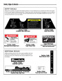
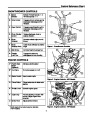
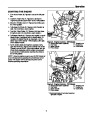
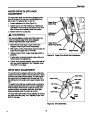
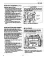
Figure 4. Engine Controls - 5HP Models
A. Electric Start Button (Optional)
B. Fuel Valve
C. Starter Handle
E. Throttle Lever
F. Engine Key
G. Choke Knob
D. Primer Button
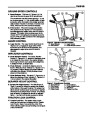
D. Primer Button - When pressed, the primer button
(D, Figure 4 & 5) provides initial fuel to help start a
cold engine. Normally, pressing the primer button
twice will provide enough fuel to start a cold engine.
E. Throttle Lever - The throttle lever (E, Figure 4 & 5)
controls the engine speed. For best overall perfor-
mance, the throttle lever should be set to the FAST
position. Use the SLOW position only for warming the
engine, or to help prevent snow/ice freeze-up when
shutting the unit down for the day.
C
D
G
F. Engine Key - The Engine Key (F, Figure 4 & 5) pre-
vents the engine from being started by unauthorized
individuals. The key must be fully inserted into the
key slot for the unit to start. The key is also used to
stop the engine by pulling the key out of the key slot.
G. Choke Knob - The Choke Knob (G, Figure 4 & 5)
adjusts the air/fuel mixture, and is used to help start a
cold engine by providing a richer mixture. Once the
engine is warm and running smoothly, the Choke
Knob should be set to the off position to provide a
normal air/fuel mix.
E
F
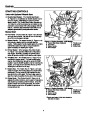
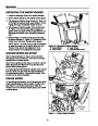
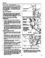
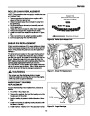
Figure 5. Engine Controls - 7HP Models
A*. Electric Start Button (Optional)
B*. Fuel Valve
C. Starter Handle
E. Throttle Lever
F. Engine Key
G. Choke Knob
D. Primer Button
*
Electric start button & fuel valve located on
right side of engine.
6
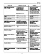
| Categories | Simplicity Snow Blower Manuals, Snow Blower Manuals |
|---|---|
| Tags | Simplicity 1693646, Simplicity 1693647, Simplicity 1693648, Simplicity 1693649, Simplicity 555, Simplicity 755 |
| Download File |
|
| Document Type | Owner's Manual |
| Language | English |
| Product Brand | Simplicity, Snow Blower |
| Document File Type | |
| Publisher | simplicitymfg.com |
| Wikipedia's Page | Simplicity Outdoor |
| Copyright | Attribution Non-commercial |
(0 votes, average: 0 out of 5)