
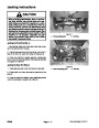

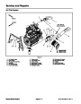
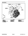
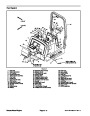
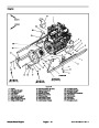
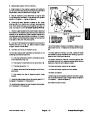
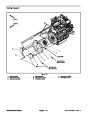


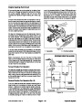
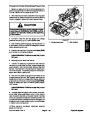
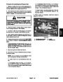
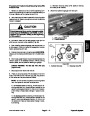
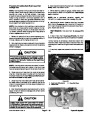
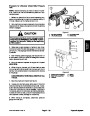

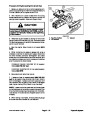
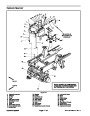
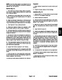
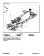

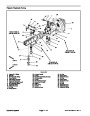

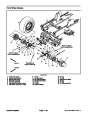


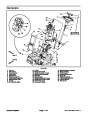
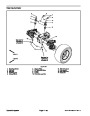
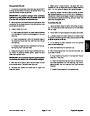


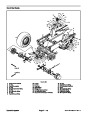


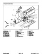
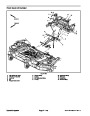
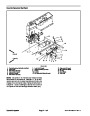
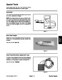
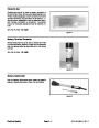
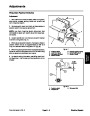
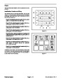
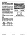
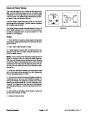
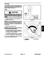
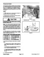
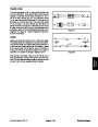
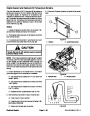
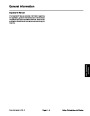
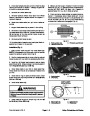
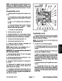
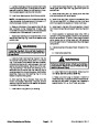
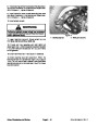
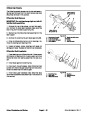
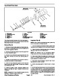
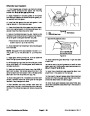
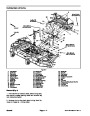
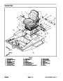
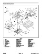


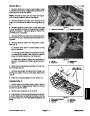

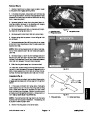
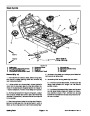
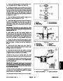


Glow Controller
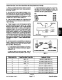
The glow controller is located under the console cover
(Fig. 39).
1
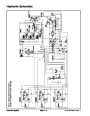
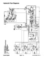
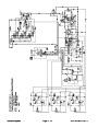
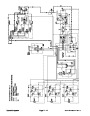
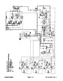
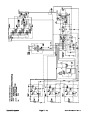
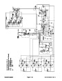
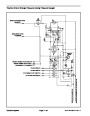
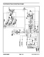
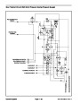
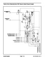
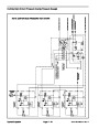
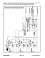
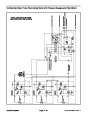
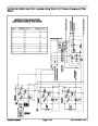
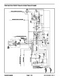
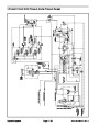
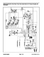
NOTE: Refer to electrical schematic and circuit draw-
ings in Chapter 9 -- Foldout Drawings when trouble-
shooting the glow controller.
2
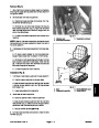
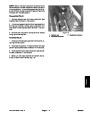
Glow Controller Operation
1.
the controller energizes the glow plugs and lights up the
glow lamp for approximately 10 seconds.
Whentheignition switch isplaced intheONposition,
2.
tion, the glow plugs will energize and the glow lamp will
When the ignition switch is held in the START posi-
not light.
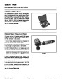
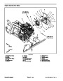
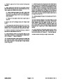
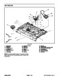
Figure 39
3.
ON, the glow plugs will deenergize and the glow lamp
will remain off.
When the ignition switch is released from START to
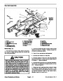
1.
Control panel
2.
Controller location
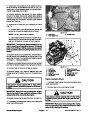
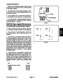
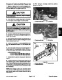
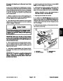
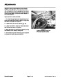
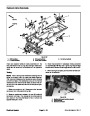
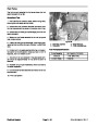
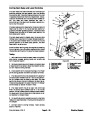
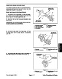
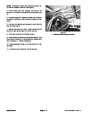
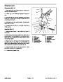
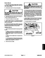
Glow Controller Checks
3
6
1.
2.
Make sure there is power from the battery.
2
1
5
4
Disconnect electrical connector totheengine runso-
lenoid to prevent the engine from starting.
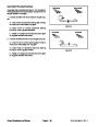
3.
PlaceignitionswitchintheONposition.Verifythefol-
lowing while in the ON position:
A. Glow indicator lamp is illuminated.
B. Glow relay is energized.
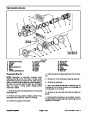
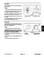
2
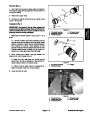
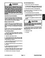
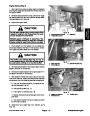
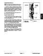
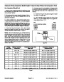
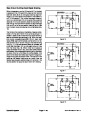
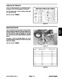
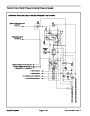
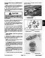
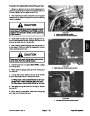
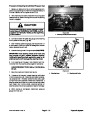
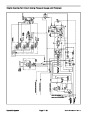
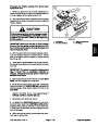
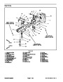
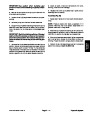
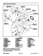
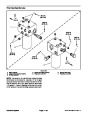
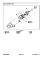
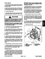
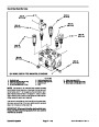
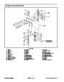
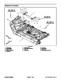
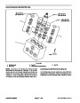
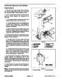
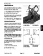
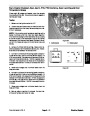
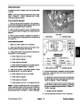
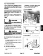
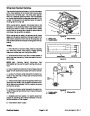
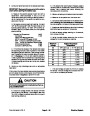
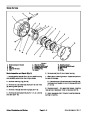
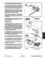
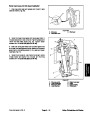
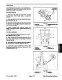
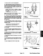
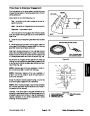
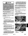
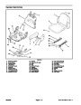
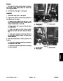
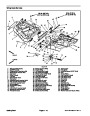
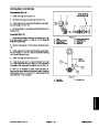
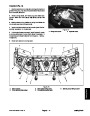
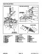
CONTROLLER
CONNECTIONS
1
START
LAMP
12V
1
2
3
4
5
6
TEMP (not used)
GLOW
VIOLET
ORANGE
BROWN
C. Glow plugs are energized.
+
GROUND
YELLOW
BLACK
D. Glow indicator lamp goes out and glow plugs de--
energize after approximately 10 seconds.
Figure 40
1.
Glow controller end view
2. Controller side view
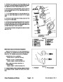
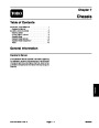
4.
Place ignition switch in the START position. Verify
the following while in the START position:
A. Glow indicator lamp is not illuminated.
B. Glow relay is energized.
5. If any of the conditions in step 3 are not met or power
to terminal 1 exists and any of the other conditions in
step 4 are not met:
A. Verify continuity ofthe circuitry from the battery to
the glow relay and glow plugs (see electrical sche-
matic in Chapter 9 -- Foldout Drawings).
C. Glow plugs are energized.
D. Power exists at terminal 1 of the glow controller.
B. Verify continuity ofthe circuitry from the battery to
ignition switch,glowcontroller,glowlamp,glowrelay
and ground (see electrical schematic in Chapter 9 --
Foldout Drawings).
NOTE: Ifthereisnopoweratterminal1oftheglowcon-
troller, verify continuity of the circuitry from the ignition
switch to the controller and perform step 4 again (see
electrical schematic in Chapter 9 -- Foldout Drawings).
C. Replace parts as necessary.
6.
Connect electrical connector to the run solenoid.
Groundsmaster 4100--D
Page 5 -- 27
Electrical System
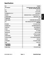
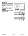
| Categories | Lawn Mower Manual, Sprinkler and Irrigation Manuals, Toro Sprinkler and Irrigation Manuals |
|---|---|
| Tags | Toro Groundsmaster 30413, Toro Groundsmaster Groundsmaster 4100 D |
| Download File |
|
| Document Type | Service Manual |
| Language | English |
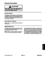
| Product Brand | Toro. Customer Service Representatives are available by phone:
Monday - Friday 7:30 a.m. to 9:00 p.m. (CDT) - Saturday 8:00 a.m. to 8:00 p.m. (CDT) - Sunday 10:00 a.m. to 8:00 p.m. (CDT)
Canada 1-888-225-4886 USA 1-888-384-9939, Lawn Mower |
| Document File Type | |
| Publisher | toro.com |
| Wikipedia's Page | Toro Company |
| Copyright | Attribution Non-commercial |
(0 votes, average: 0 out of 5)
At only 700mm wide the Mini Dumper is even at home on tight access
sites. No need to grunt, groan, and force the
mower about the yard. The US will be getting a revised 2011 Jeep Wrangler but the diesel option will not be offered in the United States.