SECTION 4: SET-UP INSTRUCTIONS
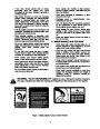
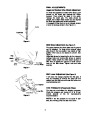
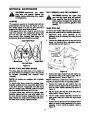
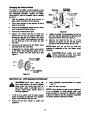
AUGER SHEAR BOLTS
Shear Bolts
The augers are secured to the auger shaft with two shear bolts
and hex lock nuts. If you hit a foreign object or ice jam, the snow
5/16-18
x 1-1/2" Long
(710-0890A)
Hex Lock Nuts shearthrowerboltsis designedand nutssoarethatprovidedthe boltsforwillyourshear.convenience.Two replacementStore in
5/16-18
(712-0429)
Thread
a safe place until needed.
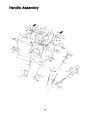
NOTE: Reference to right or left side of the snow
thrower is from behind the unit in the operating
position. Handle panel may differ from illustrations.
IMPORTANT: Check
the
adjustments
as
instructed
on
page
6,
and
make
any
final
adjustments necessary before operating your snow
thrower. Failure to follow the instructions may cause
damage to the snow thrower.
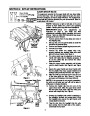
1.
Remove screws from the top sides and ends of
the shipping crate.
2.
Set top, side, and end panels aside to avoid tire
punctures or personal injury.
Wing Nuts,
Washers
and Bolts
3.
4.
Remove and discard plastic bag that covers unit.
Roll unit out of crate.
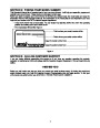
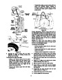
Figure 3
5. Remove the lower two plastic wing nuts,
cupped washers and carriage bolts from each
side of the lower handle. See Figure 3.
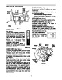
6.
The chute crank may be attached to the lower
handle with cable ties for shipping purposes, if
so cut the cable ties and remove the chute
crank at this time.
7.
8.
9.
Raise the upper handle assembly until it locks
over the lower handle. See Figure 3 and Figure
4.
Wing
Nut,
Washer
Secure the upper handle and lower handle with
the two plastic wing nuts, cupped washers and
carriage bolts previously removed. See Figure 4.
and
Bolt
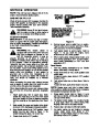
Slide the shift rod connector down over the end
of the lower shift rod. See Figure 5. Tap the
connector until it locks on the lower shift rod.
Figure 4
Upper Shift Upper Chute
Crank
Rod
NOTE: If the connector is not properly assembled,
the shift rod will pivot and you will not be able to
shift gears or change directions.
10.
Remove the hairpin clip from the end of the
upper chute crank. Slide the upper chute crank
into the lower chute crank. Align the holes, and
secure with hairpin clip. See Figure 5.
Connector
Hairpin
Clip
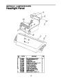
11.
Unwrap the headlight wire which is attached to
the headlight, beneath the handle panel. Wind
the headlight wire around the right handle until
excess slack is removed.
Lower
Chute
Crank
12. Plug the wire from the headlight into the wire
lead coming from the right side of the engine,
underneath the fuel tank
Lower
Shift Rod
Figure 5
5
| Categories | MTD Snow Blower Manuals, Snow Blower Manuals, Yard Machines Snow Blower Manuals |
|---|---|
| Tags | MTD 800, MTD Snow Blower Manual, Yard Machines 800 |
| Download File |
|
| Document Type | Owner's Manual |
| Language | English |
| Product Brand | Yard Machines, Snow Blower |
| Document File Type | |
| Publisher | mtdproducts.com |
| Wikipedia's Page | MTD Products |
| Copyright | Attribution Non-commercial |
(0 votes, average: 0 out of 5)