SECTION 5: CONTROLS
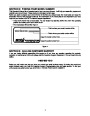
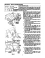
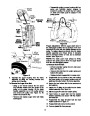
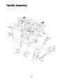
CHUTE CRANK (See Figure 9)
Traction
Drive/
Auger
Clutch
Lock
The chute crank is located on left hand side of the
snow thrower.
To change the direction in which snow is thrown,
turn chute crank as follows:
Auger
Drive
Clutch
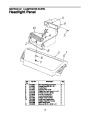
Headlight
Shift
Lever
1. Crank clockwise to discharge to the left.
2.
Crank counterclockwise to discharge to the right.
HEADLIGHT (See Figure 9)
The headlight is on whenever the engine is running.
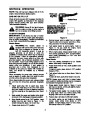
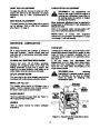
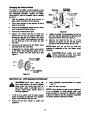
THROTTLE CONTROL (See Figure 11)
The throttle control is located on the engine. It
regulates the speed of the engine.
Chute
Crank
SAFETY IGNITION SWITCH (See Figure 11)
Figure 9
The ignition key must be inserted in the switch
before the unit will start. Remove the ignition key
when snow thrower is not in use.
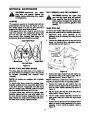
SHIFT LEVER
(See Figure 9)
The shift lever is located in the center of
the handle panel. The shift lever may be
moved into one of eight positions. Run
engine with throttle in the fast position.
Use the shift lever to determine ground
speed.
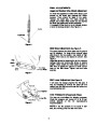
FUEL SHUT-OFFVALVE
Closed
The fuel shut-off valve, located
under fuel tank, controls fuel
flow from tank
Open
Forward—one of six speeds. Position
number one (1) is the slowest. Position
number six (6) is the fastest.
Reverse—two reverse (R) speeds. “R”
closest to the operator (all the way back)
is the faster of the two.
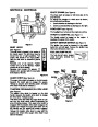
Spark
Plug
Starter
Button
Rope
Starter
Handle
Switch
Box
Figure 10
Muffler
AUGER DRIVE (See Figure 9)
The auger drive clutch is located on the left handle.
Squeeze the clutch grip to engage the augers.
Release to stop the snow throwing action. (Traction
drive clutch must also be released.)
Choke
Primer
TRACTION DRIVE/AUGER CLUTCH LOCK
(See Figure 9)
The traction drive clutch is located on the right
handle. Squeeze the traction drive clutch to engage
the wheel drive. Release to stop.
Carburetor
Cover
Ignition
Key
Throttle
Control
This same lever also locks the auger clutch so you
can turn the chute crank without interrupting the
snow throwing process. If the auger drive clutch is
engaged with the traction drive clutch engaged, the
operator can release the auger drive clutch (on the
left handle) and the augers will remain engaged.
Release the traction drive clutch to stop both the
augers and wheel drive (auger drive clutch must
also be released).
Figure 11
7
| Categories | MTD Snow Blower Manuals, Snow Blower Manuals, Yard Machines Snow Blower Manuals |
|---|---|
| Tags | MTD 800, MTD Snow Blower Manual, Yard Machines 800 |
| Download File |
|
| Document Type | Owner's Manual |
| Language | English |
| Product Brand | Yard Machines, Snow Blower |
| Document File Type | |
| Publisher | mtdproducts.com |
| Wikipedia's Page | MTD Products |
| Copyright | Attribution Non-commercial |
(0 votes, average: 0 out of 5)